"Using NI PXI, we were able to complete complex drone model simulations with low latency in real-time and perfectly simulated the interface of aviation equipment."
-Francisco Alarcón Romero, FADA-CATEC
challenge:
Build a system on the target hardware to verify the guidance, navigation and control (GNC) algorithm of the unmanned aircraft (UAV) in a real-time control simulation environment.
solution:
In the early stages of development, a hardware-in-the-loop (HIL) test environment was developed to test UAV GNC solutions.
The HIL test environment is an intermediate step in software simulation and aircraft experiments, and is critical to the development process of UAV GNC software. Through the HIL environment, engineers can test drone software in a controlled simulation environment. At the same time, it can also speed up the design and shorten the development cycle.
Through the HIL environment, engineers can discover problems that have not occurred in software simulation (mainly synchronization and timing), thereby avoiding failures in field trials and increasing the safety of the drone team.
We have developed a universal HIL platform to design verification control and navigation algorithms. The HIL test environment is fully integrated in a model-based design and development cycle (see Figure 1).
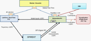
Figure 1: Schematic diagram of HWIL test environment
Model-based development
First, we designed and modified the drone platform, used it for simulation, and deployed the controller and algorithm to the hardware.
We accomplish this task based on a model-based design philosophy. This is a reliable and convenient method for system design and simulation. The use of automatic code generation tools allows us to reduce design time, easily complete the reuse of test architecture, and rapid system prototyping, thereby forming a continuous confirmation and verification process.
The purpose of the architecture includes: reuse the model without any changes on different hardware platforms; reuse the design test suite model to verify the target system; fully integrate the transparent model into the target hardware and create a system, The fast process integrates the automatically generated code into the target hardware, so that the control engineer can quickly test the model without the involvement of the software engineer (see Figure 2).
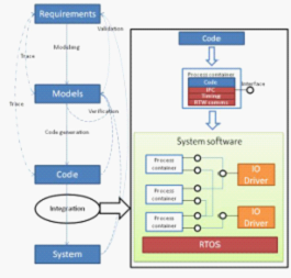
Figure 2 Model-based development process
For this project, we used Simulink®'s MathWorks software (we also used Esterel Technologies' SCADE suite) to develop the model task, and used MathWorks and Real-TIme Workshop® software for automatic coding. We need two different edits: the algorithms tested and executed in the drone are written in ANSI C code, and the mathematical model that simulates the dynamic behavior of the drone will be converted to NI LabVIEW software dynamics through the LabVIEW Simulation Interface Toolkit In the library.
In the final system, we use multiple LabVIEW I / O modules to simulate some UAV avionics and logic sensors and actuator interfaces.
LabVIEW Real-TIme PXI
PXI is a PC-based platform that can be used for test, measurement, and control, and can provide high bandwidth and ultra-low execution latency in different interfaces and buses. In this case, PXI needs to run in a complex drone model, which will be executed in the form of a dynamic library in real time. Using the PXI module in the system allows us to use the exact same interface on the drone for HIL simulation. Therefore, we will verify the GNC algorithm processing unit with the exact same configuration of the field experiment. This is very important for some systems where pure simulation is not sufficient to capture all hardware related issues (such as signal noise, errors, and synchronization issues).
GPS emulator
Through the Spirent GSS8000 GPS simulator, we can simulate and generate the same radio frequency signal emitted by the GNSS constellation satellite selected by the user. These signals will be transmitted to the real GPS sensor on the drone in the same way as the flight experiment, and can simulate the inertial sensors (accelerometer and gyroscope). We can specify different situations, degrade the signal, specify the antenna mode and simulate the IMU sensor error.
Onboard processing unit
We run a PC / 104 unit in a real-time operating system (QNX or VxWorks). The operating system contains algorithms and control strategies for testing the completion of code created by automated code generation tools and integrated architectures. We also used the same unit in a real UAV that was field tested.
Visualization
We can use Simulink External Mode software to debug the drone. Through this software, we can monitor the signal values ​​that users need to know in real time. In addition, we can change the parameters of the algorithm executed in the embedded processing unit. The interface used in operation is exactly the same as the interface used by control engineers when simulating design algorithms. As a result, the entire test environment is completely transparent, and HIL testing can be performed in the same way as field testing, thereby greatly reducing development time.
result
Comparing flight telemetry with HIL simulation using the same GNC algorithm can show the accuracy of HIL and the similarity to the real test results.
We integrated several sensors (accelerometer, gyroscope, magnetometer, GPS, and an altimeter) and a processing unit (see Figure 3) on a modified radio-controlled helicopter to transform it into a Man-machine flight test.
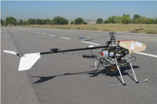
Figure 3: UAV based on CB5000 RC helicopter modified in the experiment
Figure 3: UAV modified based on CB5000 RC helicopter used in experiment Figure 3: UAV modified based on CB5000 RC helicopter used in experiment
The drone reached the reference value required by the horizontal plane without overshoot or any permanent error (see Figure 4 and Figure 5). The HIL simulation and real flight test results are extremely consistent.
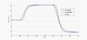
Figure 4 Comparison results of northern locations
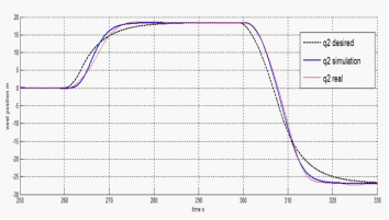
Figure 5 Western location comparison results
in conclusion
The HIL environment is very suitable for testing the entire system containing real hardware. Using NI PXI, we simulated a complex UAV model with low latency in real-time and perfectly simulated the interface of aviation equipment.
This environment can detect errors that cannot be displayed in software simulation, thereby avoiding accidents in field experiments. Because the control engineer also uses the same visualization and debugging tools in the design, development and verification process, which can quickly repeat the cycle and reduce development time.
Electronic motors specilized for roman blinds.
Roman Blinds Motors,Zigbee Tubular Roman Blind Motor,35Mm Zigbee Roman Blind Motor,Multiple Limits Roman Blind Motor
GUANGDONG A-OK TECHNOLOGY GRAND DEVELOPMENT CO.,LTD. , https://www.a-okmotor.com