With the development of computer networking and computer-level distributed application systems, the function of communication is becoming more and more important. Communication refers to the transmission of information between a computer and the outside world, including both the transfer between the computer and the computer, as well as the transfer between the computer and external devices such as terminals, printers, and disks. In the field of communication, the number of data bits per data transmission in data communication can be divided into: parallel communication and serial communication.
Serial communication refers to the use of a data line to transmit data one bit at a time, each bit of data occupying a fixed length of time. It requires only a few lines to exchange information between systems, especially for long-distance communication between computers and computers, computers and peripherals. In serial communication, each character sent and received is actually transmitted one bit at a time, each bit being 1 or 0.
MIPI D'Phy is a physical serial communication layer used to connect an application processor to a display or camera. As a physical layer, it has many advantages.
The MIPI (Mobile Industry Processor Interface) Alliance is a non-profit organization dedicated to building hardware and software interface standards in mobile devices. Its vision is to develop the world's most comprehensive set of interface specifications for mobile and mobile-affected products, maximizing design reuse, driving innovation, reducing time-to-market, and helping to increase products from companies. Interoperability between.
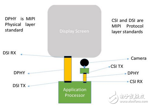
Connection diagram of camera and display and application processor in mobile phone
MIPI D'Phy is a physical serial data communication layer that runs protocols such as CSI (Camera Serial Interface) and DSI (Display Serial Interface). It is physically connected to the camera sensor and application processor (for CSI) as well as the application processor and display (for DSI), as shown above.
D'Phy is a high-speed, low-power source-synchronous physical layer that is ideal for power-hungry battery-powered devices due to its high-efficiency design. It also includes high-speed modules and low-power modules that help achieve high efficiency. The payload data (image data) uses a high speed module, and the transmission of control and status information (between the camera/display and the application processor) uses a low power module (using low frequency signals). It has the special ability to send high speed and low power data in a single packet pulse. Low-power modules help save power, and high-speed modules help achieve the higher bandwidth required for high-resolution photo quality data signals.
D'Phy's architectureTo meet the high bandwidth requirements of HD quality images, MIPI D'Phy includes a clock channel and a number of data channels that can be set (up to 4 channels). Bandwidth can be increased by increasing the number of data channels. By increasing the number of channels, the same amount of data can be transmitted over multiple channels in a shorter amount of time. MIPI D'Phy uses a forward source synchronous clock, which is used by all data channels of the D'Phy receiver to capture high speed data signals.
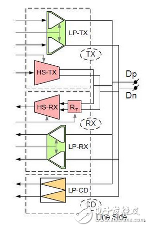
Universal D'Phy channel
In order to meet both low power and high speed requirements, each data channel of the general-purpose D'Phy IP (shown above) is used by low-power transmitters (LP-TX), high-speed transmitters (HS-TX), It is composed of a serializer that sends MIPI D'Phy special patterns. The receiving side is composed of a low power receiver (LPRX), a high speed receiver (HS-RX), a deserializer, and is used to receive these MIPI D'Phy special data signals. Consisting of a low power contention detector (LP-CD).
The clock channel consists of a low-power transmitter (LP-TX), a high-speed transmitter (HS-TX) for transmitting MIPI D'Phy special clock channel patterns, and a low-power receiver (LP RX), high-speed on the receiving side. The receiver (HS-RX) consists of a low-power contention detector (LP-CD) for receiving these MIPI D'Phy special clock signals.
Each data channel (or clock channel) of the receiver is connected to the transmitter by two wires Dp and Dn (or Clkp and Clkn). Both high-speed and low-power data transmissions are performed on the two wires that connect the two communication modules.
The low-power module is an unterminated module that operates in a single-ended mode and uses a logic voltage of 1.2V. The data rate of the low power signal used to provide control and status information is less than 10 Mbps.
The high speed module works in differential mode. They use a low voltage swing load data signal to transmit information (the high speed signal - Dp - Dn - typical differential output swing is 200mV). This type of module is typically terminated on the die, typically between 100 and Ω between Dp and Dn.
How D'Phy works and the flow of data between the camera output to the MIPI D'Phy receiver
The image data captured by the camera sensor is processed by the MIPI transmitter and transmitted over multiple data channels. The number of data channels used for data transfer is configurable.
The transmitter organizes the image data according to the number of data channels used for data transmission. The transmitter then serializes the data on each channel and sends it to the corresponding receive channel.
For example, if two channels are used, the first byte of payload data is sent on data channel 0 and the second byte is sent on data channel 1. Also on the receiving side, serial data from each data channel is converted to byte format with the help of a deserializer used in each receive channel of D'Phy. The bytes from each channel deserialized are then merged together by the CSI controller.
Before each high-speed payload data pulse appears on each channel, the transmitted D'Phy will insert a synchronization sequence (00011101), as shown in the following figure. This synchronization sequence is used by the data channel receiving D'Phy to establish synchronization with the high speed payload data. The payload data is forwarded to the MIPI CSI 2 controller only when the synchronization signal is correctly decoded by the receiving D'Phy, completing further processing of the data.
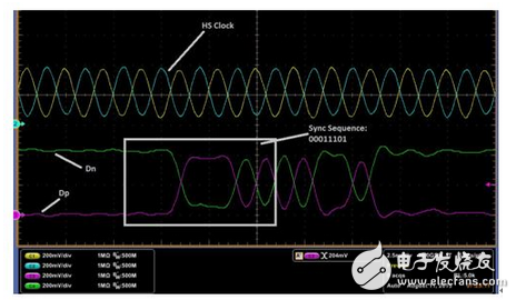
Send synchronization sequence in the pattern
As part of the D'Phy initialization, initially all channels remain in the LP11 state (1.2V level) for a specific period of time. This LP11 state is also referred to as a stop state. After that, in order to send the image data, the transmitter sends a specific sequence to the receiver, causing the receiver channel to enter the high speed mode from the low power mode. The high-speed entry sequence consists of driving the LP11-"LP01-"LP00 (LP-"HS conversion) on the receiver channel as shown below. After successfully receiving this sequence, the high speed receiver module activates its terminal to receive high speed differential data.
Now that the high speed receiver terminal is active, the receiver begins to receive high speed data from the transmitter. However, after the LP-"HS conversion, the transmitter will send HS Zeros (V(Dn)"V(Dp)) for a specific period of time to ensure that the receiver is properly activated before any payload data is sent. .
Once the receiver is activated, the high speed receiver continuously receives data until it encounters the LP11 state on its channel. The LP11 state brings the data channel back from high speed mode to low power mode.
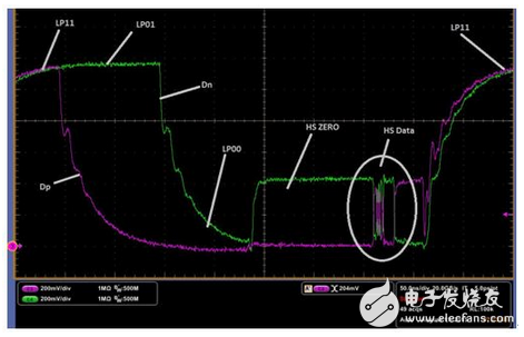
High-speed pulses on the data path describe LP to HS conversion and HS Zero
The payload data sent through the D'Phy data channel is in the format of the data packet. It can be a long packet or a short packet. The long packet contains a 32-bit header, payload data, and a 16-bit packet footer. Short packets contain only 32-bit headers.
The data channel enters the LP11 state after each high-speed burst. A single high speed pulse represents data corresponding to the horizontal line of an image, while the LP11 state between high speed pulses represents the blanking period. Because low power commands require signals to be sent at a lower frequency, this intermittent motion of D'Phy between low power and high speed modes helps to reduce overall power consumption.
When there is no data to transmit, all channels remain in the ULPS state (ultra-low power mode). This is a special low power mode that helps to further reduce power consumption. The ULPS state is entered through a specific low power mode. Once in the ULPS state, all channels are driven low (0V). The ULPS entry mode of the clock channel and the data channel are different.
Timing relationship between differential clock and dataThe high speed payload data from the transmitter is transmitted on both edges of the high speed differential clock (DDR clock) as shown in the following figure. The high-speed differential clock and data transmitted by the transmitter are 90 degrees out of phase, and the data is sent first. This timing relationship between the clock and the data helps to achieve the setup and hold time requirements of the receiver data channel.
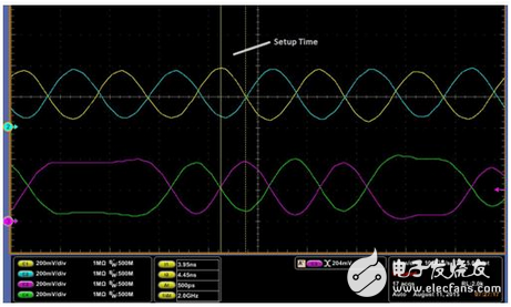
Timing relationship between clock and data
Summary of this articleMIPI D'Phy, a physical serial communication layer, features low-power operation and is therefore increasingly attractive for today's power-hungry mobile and mobile-related applications.
Universal Remotes,Universal Remote Control,Ir And Rf Universal Remote,Best Universal Remote Control
Shenzhen Chaoran Technology Corp. , https://www.chaoran-remote.com