The self-developed laser tracking measurement system realizes coordinate measurement of spatial targets by laser ranging and precision angle measurement. As a precision angle measuring and distance measuring instrument, the laser tracking measurement system needs to be calibrated before leaving the factory to obtain the relevant parameters of the internal optical system, mechanical structure and servo system of the instrument, and evaluate the measurement accuracy of the instrument. In order to make the instrument calibration process simple and effective, it is necessary to develop a universal calibration software. LabWindows/CVI is a virtual instrument software development tool introduced by NI Corporation of the United States. It provides an ideal software development environment for technical developers familiar with C language to establish computer instrument system-virtual instrument in the field of measurement and control. The software is used in a wide range of applications, including military, telecommunications, industrial production and aerospace [1-2]. In this paper, virtual instrument technology is used to develop a calibration software based on LabWindows/CVI for the self-developed laser tracking measurement system.
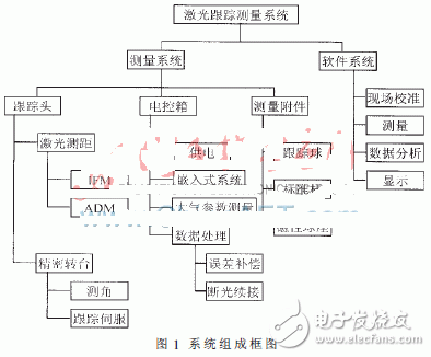
1 System composition and calibration content
The hardware of the laser tracking measurement system mainly includes tracking and measuring unit (including tracking head, bracket, etc.), electronic control unit (including electric control box, environmental sensor, etc.), main control computer and measuring accessories (including corner reflector, par, magnetic Base, etc.), as shown in Figure 1. Among them, the tracking head is the core unit of the laser tracking measurement system. It integrates the laser range finder (interference ranging and absolute ranging) and the photoelectric theodolite, and can realize the functions of ranging, angle measurement and tracking at the same time. The purpose of the laser tracking measurement system calibration is to identify the error items that affect the system ranging and angle measurement accuracy for software correction. According to the degree of change within the internal parameters of the system, it can be divided into laboratory calibration and on-site self-calibration. The laboratory calibration is mainly to calibrate the IFM laser, the atmospheric parameter sensing device and the angle grating encoder; the on-site self-calibration is mainly to calibrate the home reference distance, geometric error and ADM ranging. Since some of the above calibration items have high requirements on the experimental environment, the calibration software only involves calibration of items such as Home reference distance, geometric error, ADM ranging, angle grating code disc, and other angular accuracy inspection and system accuracy detection ( The Bundle test) will also be placed in the calibration software.
2 calibration software design
2.1 calibration software overall design
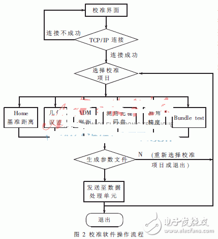
The TCP/IP connection is made via Ethernet between the calibration software and the laser tracking measurement system. When the software is running, first connect the device, then select the calibration item. After the calibration sub-interface pops up, follow the prompts. After the calibration is completed, return to the main interface to generate and send the parameter file. After successful, exit the main interface and complete the user self-calibration. . The operation flow of the calibration software is shown in Figure 2.
2.2 Calibration software modular design
2.2.1 main interface design
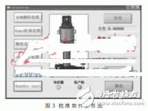
The calibration main interface design is based on the principle of simplicity and practicality. The main functions are device connectivity, calibration project selection, parameter file generation, connection status display, and real-time measurement data display, as shown in Figure 3. When the device connection is not implemented, the other buttons are locked except for the connect and exit buttons on the main interface. When the connection button is clicked and the status lights of the electronic control box and the client turn green, other buttons are available. When the measurement system has data output, the azimuth, elevation and distance display of the data display area will change synchronously. When a calibration item button is clicked, the calibration item sub-interface will pop up. The user only needs to follow the prompt on the sub-interface. During the whole process, the other calibration item buttons will be locked until the user exits the current calibration item.
(1) TCP/IP connection
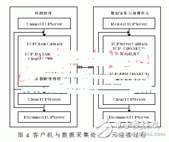
Communication between the calibration software and the device is done via Ethernet. LabWindow/CVI provides functions for implementing TCP/IP communication between devices. According to different service objects, it can be roughly divided into three categories: server functions, client functions, and support functions [3]. The calibration software plays the role of the client in the laser tracking measurement system. It not only receives the data sent from the data acquisition and processing unit (server side) of the tracking measurement system, but also responds and sends data to the server. The function completed by the TCP/IP connection button is to start the connection program, connect according to the set server port number and IP address, receive the data sent by the server and solve the display. After the connection is successful, the electrical control box and client indicator will turn green. If there is data on the server side, the azimuth, pitch and distance values ​​will be refreshed continuously, and the refresh rate is ≤1 000 Hz. The connection process between the TCP/IP calibration software (client) and the data acquisition processing unit (server) is shown in FIG.
(2) Calibration item selection
The calibration software has six items, namely ADM ranging calibration, HOME distance calibration, angle error checking, GEC geometric error calibration, angle dial calibration and Bundle test system accuracy detection. There is an interlock relationship between the calibration item buttons, that is, when any button is clicked, other item buttons will be unavailable until the current calibration item is exited.
(3) Parameter file generation
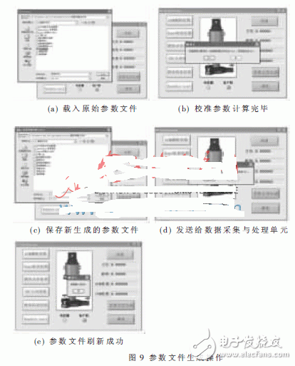
After executing some calibration items, clicking the parameter file generation button will enter the new parameter file generation process: load the original parameter file - calculate the corresponding calibration parameters based on the execution of the calibration project - generate a new parameter file - send a new parameter file to Data Acquisition Processing Unit - Save Original Measurement Data - Exit the parameter file generation program.
2.2.2 Calibration project sub-interface design
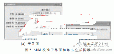
Due to the large number of calibration items, only the ADM ranging calibration is taken as an example to illustrate the design of the sub-interface. At the user measurement site, after the laser tracking measurement system is started, the target is placed in a suitable position, and the ADM and IFM ranging values ​​are observed. If the difference between the two is large and the variation is unstable, ADM ranging calibration is required. The method used is to compare with the IFM ranging of the laser tracking measurement system, and the cubic curve function is used to fit the error curve. In order to ensure the measurement accuracy, the number of measurement points is required to be no less than 6 points, and the total length is up to 36 points, and the measurement point interval is preferably 1 m. When the angle and distance data meet the requirements of the set measurement point, the measurement data turns green, prompting the operator to collect the point, click the capture button, the current data is saved and the next operation prompt is popped up. Figure 5 shows the ADM ranging calibration sub-interface and pop-up operation prompts. The other calibration item sub-interface design is similar to the ADM calibration sub-interface.
2.2.3 Calibration software parameter file design
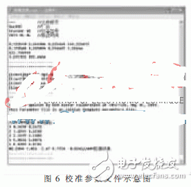
The parameter file is a file used in the laser tracking measurement system to store servo control parameters, error correction and calibration parameters, and other important parameters such as laser calibration wavelengths. The system will give a default parameter file for error correction before leaving the factory. In the process of using the system, in order to ensure the stability and reliability of the environment when the system works in the field, some data in the parameter file allows the user to refresh after calibration by the calibration software as needed. The parameter file is divided into three parts according to the content: parameter area, parameter description area and calibration history area. After the user performs calibration, the part of the parameter file that is changed is the parameter area and the calibration history area. The parameter file is saved in a text file (*.txt). Figure 6 is a schematic diagram of a parameter file.
3 calibration software joint experiment
Based on the equipment developed by the existing laser tracking measurement system, the joint experiment of calibration software and data acquisition and processing unit is carried out. The required equipments are: two computers, one data acquisition and processing unit and several connecting lines, one of which is used as the upper computer (calibration software), connected by the network cable and the data acquisition and processing unit, and the other as the data acquisition and processing unit. The program refreshes the device. The experimental content is data connectivity experiment, instruction transmission experiment and parameter file refresh experiment. The data connectivity experiment refers to the TCP/IP connectivity and measurement data solution display experiment between devices; the command transmission experiment refers to the control command transmission and execution successful return test in the calibration software; the parameter file refresh experiment refers to the calibration software for data collection. Experiment with the refresh operation of the processing unit parameter file area.
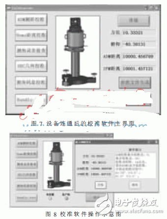
After the device is connected, the electrical control box and the client status light turn green. On the main interface of the calibration software, except for the connection button, other buttons can be operated, as shown in Figure 7. When one of the calibration items is selected, the operation sub-interface of the item is popped up, and other buttons on the main interface are unavailable (except the exit button) until the current sub-interface is exited, as shown in FIG. After the user performs the required calibration items, he can click the parameter file generation button to generate, store and send the new parameter file. Figure 9 shows the software operation process after the click parameter file is generated.
Aiming at the calibration requirements of the self-developed laser tracking measurement system, a calibration software for measurement users based on LabWindows/CVI was designed. After the laser tracking measurement system is started, the measurement user automatically checks the ranging angle error through the calibration software to determine whether calibration of the relevant items is required. Based on the principle of humanized design, the software automatically guides the user to complete the calibration of the corresponding project during the calibration process, and can display and store the original measurement data and calibration parameters to realize the automation and virtualization of the entire calibration process.
ZGAR Vape Pods 1.0
ZGAR electronic cigarette uses high-tech R&D, food grade disposable pods and high-quality raw material. A new design of gradient our disposable vape is impressive.We equip with breathing lights in the vape pen and pods.
Our team has very high requirements for product quality, taste allocation and packaging design. Designers only use Hong Kong designers, e-cigarette liquid only imports from the United States, materials are food grade, and assembly factory wants medical grade without ground workshop.
We offer best price, high quality Pod System Vape,Pods Systems Touch Screen,Empty Pod System, Pod Vape System,Disposable Pod device,Vape Pods to all over the world.


ZGAR Vape 1.0 Pods,ZGAR Vape Pods 1.0 ,Pod Systems,Atomizer, E-cigarette, Empty Pod Vape Manufacturer and Supplier in China
Zgar International (M) SDN BHD , https://www.zgarvapepen.com