FPGAs are often used to perform sequence- and control-based actions, such as implementing a simple communication protocol. For designers, the best way to meet these actions and sequence requirements is to use a state machine. A state machine is a logical structure that converts between a limited number of states. A state machine is only in one state at a particular point in time. But under the trigger of a series of triggers, it will be converted between different states.
In theory, state machines can be divided into two categories: Moore state machine and Mealy state machine. The only difference between them is how to generate the output of the state machine. The output of the Moore state machine is only a function of the current state. A typical example is the counter. The output of the Mealy state machine is a function of the current state and input. A typical example is the Richards controller.
Defining state machine
When you need to define a state machine, you first need to draw a state diagram. State diagrams can be used to display status, transitions between states, and output from state machines. Figure 1 shows the state diagram of the Moore state machine (left) and the state diagram of the Mealy state machine (right).
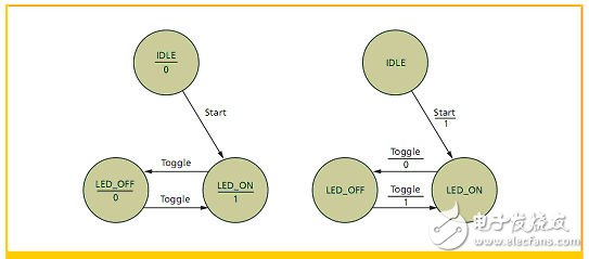
Figure 1 State diagram of the Moore state machine (left) and the Mealy state machine (right) for turning the LED on/off.
If you want to implement these state diagrams in physical components (as engineers did before the FPGA came out), you first have to generate the current state and subsequent state tables, and then generate the logic needed to implement the state machine. But since we will use FPGAs to implement the design, we can start working directly from the state transition diagram.
Algorithm state diagram
Although many state machines are designed using the state diagram method shown in Figure 1, there is another way to describe the state machine behavior, which is the algorithm state diagram method. The ASM diagram (Figure 2) is closer in appearance to the software engineering flow diagram. It consists of three basic parts:
1. Status box. It is related to the state name and contains a list of Moore state outputs.
2. Decision box. If the check condition is true, the next state is judged.
3. Conditional output box. Let the state machine describe the Mealy output based on the current state and input.
Some engineers believe that if a hardware description language such as VHDL is used, the state machine described in the ASM format is easier to map into the implementation.
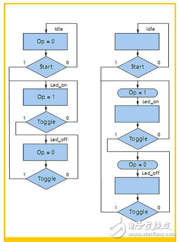
Figure 2 is an algorithm state diagram for the state machine (Moore state machine (left), Mealy state machine (right)) shown in Figure 1.
Busway Temperature Monitoring System
The busway temperature monitoring system is composed of monitoring host and temperature and humidity acquisition module, which is used for the temperature monitoring of low-voltage dense busway. The main monitoring temperatures include: the temperature at the busway connection (the temperature of each phase contact point), the busway housing temperature, and the ambient temperature, and can display, upload, store and fault alarm the data in the monitoring unit.
Busway Temperature Monitoring System,Thermostatic Temperature Control Valve,Temperature Control Box Mod,Bus Bar Temperature Monitoring
Jiangsu Sfere Electric Co., Ltd , https://www.elecnova-global.com