The formation of charge and discharge is one of the key processes in the battery production process, and its control level is directly related to the quality of the product. The process requires that the charger can charge and discharge the battery multiple times according to conditions such as time, voltage or ampere-hour, and has various charging and discharging modes such as static electricity, constant current charging, constant voltage (current limiting) charging, constant current discharging, and the like. And required to achieve control accuracy ≤ 1%, detection accuracy ≤ 0.5%, current limit voltage protection accuracy ≤ 2%. In the conventional production mode, manual manual operation is mainly used, the control precision is low, the labor intensity is large, and the human factor has great influence on the quality of the product. Therefore, the introduction of the microcomputer program control device is of great significance for improving the operation process and improving the product quality. [1]
With the development of new types of microcontrollers with large-capacity FlashROMs, various serial ADCs, DACs, and high-density serial E2PROMs, it is possible to develop high-performance, low-cost, compact battery charge and discharge controllers. According to the needs of small-capacity multi-loop charger equipment, this paper proposes a design scheme of multi-loop microcontroller composed of embedded single-chip microcomputer and its peripheral serial devices, which can simultaneously control the operation of 4 formation chargers and realize automatic Control functions such as static electricity, constant current charge and discharge, constant voltage current limit charging; use Chinese character LCD display, can control program parameters through keyboard setting, and have multiple stages of functions that can be controlled automatically by time and condition (voltage, current or ampere-hour) After the power is cut off, the state can be automatically memorized, and the original process is automatically resumed after the operation is resumed; the faults such as current interruption, overcurrent and overvoltage are automatically monitored and alarmed; in addition, two levels of centralized monitoring and dispersion can be formed through RS485 serial communication and upper computer networking. Type system. [2-4]
Controller hardware designThe hardware of multi-loop into a charge and discharge controller is mainly composed of two main parts: a main control module and a process processing module. According to the design requirements, the main control module should have the following functions: (1) good human-computer interaction interface, including keyboard and display; (2) storage process control parameters; (3) power-down save operation status and data; (4) high Reliability and anti-interference; (5) Networking with the host computer to form a two-level centralized monitoring or print recording system. The process processing module completes the conditioning, isolation, and conversion of the input/output signals of the 4-way into a charger. It includes the output of the system's given control, the input of current and voltage samples, and the output of the switch. According to the above functional requirements, the hardware structure of the design controller is shown in Figure 1.
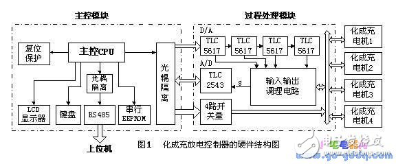
The main control module is based on low-power, high-performance single-chip AT89C55 CPU, its internal flash memory capacity reaches 20KB, internal RAM 256 bytes, can meet the needs of more complex control programs, LCD display Chinese character library and communication programs, without Extend external program memory and data memory. The panel of the main control module provides 2&TImes;7 membrane keyboard and 192&TImes;64 dot matrix liquid crystal display, which makes the field operation screen very friendly.
The large-capacity 24LCXX series serial E2PROM is used to store a large number of set process control parameters and power-down status data. The interface between 24LCXX and MCU uses a two-wire serial bus, which is simple and reliable. The one-chip computer is used as the master device, 24LCXX is used as the slave device, and the master device reads and writes data to the slave device.
The process device interface adopts serial chip, the interface is simple, and the signal line between the MCU and the MCU is up to four, which greatly reduces the number of wires, and these signal wires are isolated by the optocoupler and then connected to the MCU, which improves the reliability of the system. .
In addition, considering the characteristics of the control system, it belongs to the multi-point communication mode, and the distance is long, and the data requires two-way transmission. Therefore, the RS-485 standard interface with convenient connection, good anti-interference performance, low distortion and low cost is adopted. Data communication between the host computers.
The hardware design of the microcontroller fully embodies the compact structure of the embedded system, simple peripherals, small size, convenient carrying, and greatly reduced cost.
Data storage managementIn the process of controlling the operation of 4 chargers, it is necessary to save a large amount of non-volatile data, such as process control parameters and operation control data. The parameters of the preset 8 groups of models are saved in the serial E2PROM, and each group contains 12 stages of process control parameters. During the control of the operation of the charger, the system periodically saves the operating parameter values ​​of each circuit charger to the E2PROM. When the system suddenly loses power, it can automatically remember the state, and resume the original process automatically after the operation is resumed.
However, in consideration of the randomness of the power failure, in order to ensure the correctness and integrity of the data, a specific flag is set to ensure the integrity of the written data. That is, each time before the 24LCXX operation, the flag is first determined. If it is FFH, it indicates that the basic data area data is complete, and its content is written into the backup data area; if it is 00H, it indicates that the last operation of the basic data area is interrupted. If the data is incomplete, the contents of the backup data area are written to the basic data to restore the data state before the power is turned off. After the data operation is completed, the flag is set to FFH, indicating a complete operation of the data. This method of locking data operations effectively ensures stable operation of the system.
4 controller software design4.1 Real-time multitasking structure and task division
The controller software adopts real-time multi-tasking structure and is divided into two parts: startup management task and operation task. The startup management tasks include power-on command processing (auxiliary self-test, clear memory data, etc.), system initialization and process control parameters, etc., while the serial communication interrupt task acts as a background task, receives the host computer command and sends status information to the host computer. The running task is activated after executing the startup charger command, including the master scheduler (foreground task), system timer interrupt, serial communication interrupt task, etc., and is scheduled to run according to different priorities (the foreground task is interrupted by the background task). Figure 2 is a schematic diagram of system tasks and scheduling.
Background task 1 generates an interrupt every 100 ms by system timer T0, forming a basic clock source, providing various software counters for control and communication tasks. The master scheduler schedules each task according to the timer count state and controls the operation of the 4-way charger. These tasks include: scanning the keyboard every 1 second, activating the corresponding tasks according to the commands entered by the keyboard, such as starting or terminating the process, displaying the setting parameters, etc.; routinely collecting and processing the routine data every 1 second, respectively collecting 4 charging machines The voltage and current quantities are processed accordingly. The real-time working status parameters of the 4-way charger are displayed every 1 second, including the current working phase, working mode, running time, voltage and current value, and safety hours. Wait; calculate the number of hours of the four-way charger every 2 seconds; perform closed-loop feedback control PI adjustment every 3 seconds; accumulate the number of hours of the four-way charger every 1 minute, and back up the relevant data to the E2PROM in. During the operation, the current and voltage signals are checked regularly. If there are abnormalities, interruptions, overcurrents, overvoltages, etc., the fault type and the corresponding charger number are displayed in time.
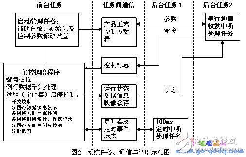
Background task 2 is a serial communication interrupt task. Due to the use of master-slave asynchronous serial communication, the priority of the communication interrupt task is higher than the priority of the timer interrupt. Communication interruptions include receiving interrupts and transmitting interrupts, and need to perform switching control and processing as needed. Usually in the receiving interrupt enable state, when receiving the polling message from the host computer, the organization sends a message, sends the message frame to the sending buffer, starts the sending interrupt and sends the counter, and presses the counter in the subsequent sending interrupt task. Sending a byte will not send a interrupt until the frame is sent. If the host computer data/command message header is received, the acknowledgment buffer is cleared and waiting for the next interrupt byte to be received.
4.2 modular software design
The controller's software design uses a modular structure to make the program clear and concise. At the same time, the modules are relatively independent and can be debugged separately. When the program is expanded, do not change the original structure, just modify the corresponding module. According to the division of the system tasks in FIG. 2, the program module is mainly composed of a main control program and a timer interrupt program module, a communication program module, a display and keyboard processing module, an input and output, and a control quantity calculation module. The connection between each module is to use the logic processing function of the single chip microcomputer, set the flag bit, and control and call by querying the operation of the flag bit.
Due to the length of the space, the process of each module work will not be described in detail.
5 communication system designThis paper is applied to the battery factory's plate or sealed battery charge and discharge control device. In order to reduce the cost, facilitate management and improve system reliability, the control system design can adopt a small distributed control system, that is, two-layer structure: more dispersed The loop controller is equipped with an operating station (commonly known as the upper computer and the lower computer). Through the low-cost, high-reliability RS-485 real-time communication network, dozens of multi-loop controllers are connected to the PC to achieve centralized monitoring of the production process. The communication between the upper computer and the lower computer includes data downloading, data loading, command delivery, and the like. The communication system is designed as follows:
(1) The system physical layer protocol adopts the RS-485 standard. In order to increase the communication rate as much as possible within the allowable range, the baud rate selects a non-standard 3125 bps. When the host computer uses software polling mode to communicate with 20 field controllers one by one, through proper software design, it can basically meet the real-time requirements of the charging and discharging process operation.
(2) According to the link layer protocol reference HDLC, short frame fixed length transmission is used, and the effective byte per frame is 7. The application layer requires functions such as instant data uploading, historical data loading, control parameter data downloading, and command delivery.
(3) The system adopts the master-slave mode of the primary station polling, and the primary station initiates communication without network conflict; the secondary station selects the secondary station that it requires to communicate, and each station can have different priorities. This approach is easy to understand and implement relative to a bus-based control network.
6 ConclusionThe experiment and the actual operation of the field show that the multi-loop into a charge and discharge controller has a good man-machine dialogue window, simple structure, simple operation, flexible parameter setting and strong adaptability. The system software and hardware equipment works normally, with complete functions, stable and reliable, and has perfect system self-diagnosis and fault location functions. Moreover, it has the characteristics of low cost and small size (80 & TImes; 160 & TImes; 100).
Computer Monitor Stand, the multi-point silicone support surface is more non-slip, and the multi-point soft silicone design prevents the computer from scratching while anti-slip. Laptop Stand Amazon is lightweight design, the weight of about 10kgs is equivalent to the weight of a large number of mobile phones, easy to store and go whenever you want.

Monitor Stand Riser,Metal Desk Monitor Stand Riser,Dual Monitor Riser Stand,Universal Monitor Stand Riser
Shenzhen ChengRong Technology Co.,Ltd. , https://www.laptopstandsuppliers.com