1 Introduction
In the test system, it is often necessary to centrally control multiple instruments and equipment, and perform unified analysis and processing on their data. The increase in the degree of intelligence and automation of the test system puts forward higher requirements for data exchange between test equipment. Here, distributed control has become a very effective way [1].
In a distributed test system, data exchange is mainly performed between the main processor and each intelligent control unit. According to the characteristics of the test system, its communication system should have good reliability, versatility, scalability and simple connection methods, and It should be able to adapt to the needs of long-distance transmission. The above characteristics should be fully considered in the formulation of system communication methods and protocols to adapt it to the needs of different test applications.
In order to meet the needs of multiple control nodes and long-distance communication, this article uses RS-485 half-duplex serial communication protocol as the communication standard of this test control network. Due to the use of balanced driving and differential reception, the effects of common mode interference are effectively reduced, so that its transmission distance and load capacity are greatly improved compared to RS-232C [2].
Since the current PCs are equipped with RS-232C interface, an RS-485 interface is designed, which can be placed in an ordinary adapter and directly plugged into the serial port of the PC to output the RS-232C of the PC Converted to RS-485 output, its structure is shown in Figure 1. Compared with other methods, this method has the advantages of simple interface, strong versatility, small size and low cost. In addition, we can also add an intelligent control unit to this interface to meet the needs of communication with conventional instruments.
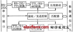
Figure 1 Serial interface adapter
3 Data transmission protocol and software design
In the distributed test system, each test equipment mainly communicates with the main processor. According to this feature, this paper decided to adopt a more clear master-slave communication as the system communication method [3], in order to maintain the unity of the system and At the same time to meet the needs of communication between the remaining nodes.
3.1 Information frame format
The transmission of data and commands in the system are all packed, and the data frame format is shown in Figure 2. Among them, the highest bit of the address byte is specified as 0 to mark the beginning of the frame; the variable length data field is used, and the data length range is 1 to 255 bytes; two bytes are used for data verification; the tail flag is specified as 0FFH , To mark the end of the frame. The byte transmission format is specified as 11 bits, that is, 8 data bits, 1 address / data flag bit, 1 start bit and 1 stop bit. In order to facilitate multi-machine communication, the transmission bytes are divided into address code and data code. The 9th bit flag of the address code is 1, which can be received by all lower computers in the listener state; the 9th bit flag of the data code If it is 0, it can only be received by the designated lower computer.
In communication, the commands and data sent by the host can be divided into address commands for designated lower-level machines and general commands for all lower-level machines. For this reason, we stipulate the address 7FH as the general address, and the commands sent to this address can be received by all the lower computers. In order to ensure reliable data transmission, the communication is carried out in response mode. After receiving the data sent by the host computer, the lower computer immediately sends back the status information. If the response message is not received within the specified time, a timeout alarm will be issued. In this system, 4 bytes are agreed to represent the communication and working status of the system. Among them, two bytes represent the communication status, and two bytes represent the current working status of the controller, which can be adjusted according to the specific application. Here, the CRC method is used for data verification. When a data transmission error is found, the host uses an automatic feedback retransmission method to correct it.
![]()
Figure 2 Data communication frame format
3.2 Interrupt-based communication software design
In order to ensure the time for the main processor to perform data processing and other work, the communication process should minimize its impact. Therefore, in software design, the main process is interrupt driven. When sending information, you only need to write data to the buffer, and the subsequent process is taken over by the interrupt; similarly, the receiving process is also completely managed by the interrupt, so that the host does not need to wait for any other processing. In order to adapt to different communication tasks, especially the needs of large amounts of data communication, the receiving and sending parts have adopted a ring buffer structure. In order to make full use of hardware resources, the main process is written in assembly language, and the method of combining embedded assembly and assembly call is used to write C language communication function to realize the interface with high-level programs. In addition, each main communication process constitutes an independent communication function, which can be used in any communication network adopting this protocol. Figure 3 shows the serial port interrupt processing flow. Here, the data is sent and received in a byte-by-byte manner to avoid centralized occupation of the host's working time.
Using the above communication protocol and software, based on the bus network, we conveniently realized the data communication between the PC and between the PC and the intelligent instruments. Experiments prove that they have good adaptability.
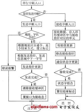
Figure 3 Serial port interrupt processing flow
4 Application of network communication in detection system
In a comprehensive test system, it is often necessary to centrally and uniformly control multiple sensors and actuators. In addition, the host is mainly used for data processing and analysis and calculation, and the control process should not affect the above process. In general, the system should be able to control as many nodes as possible and should have a certain expansion capability to facilitate the addition of new test equipment.
For the above control requirements, the hardware centralized method is often adopted, that is, the hardware circuit is composed of a centralized controller to control the actions of the actuator and other actuators. It has the advantages of centralized function and fast speed, but also has complex logical relationships, poor flexibility, and failures that are not easy to eliminate Wait for many shortcomings. It can be seen from the foregoing that such a system can be regarded as a distributed system composed of multiple sensing test units and actuators. Using the above network communication design ideas, we can decentralize the system control function to each test unit and execution mechanism, thereby forming a distributed test control system based on half-duplex communication with the system main processor as the main controller.
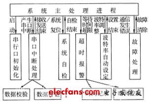
Figure 4 The relationship between the application process and the main communication module
Using the communication protocol and software described above, after a specific set of command codes for this control system is agreed, the host can control each execution mechanism. Due to the use of all interrupt-driven design methods, the system communication process will not affect the host's processing. The relationship between the main processing process of the system and some communication modules is shown in FIG. 4. Practical application shows that compared with the original method, the performance of the control system can be greatly improved.
5 Conclusion
This article aims to study a more widely adaptable data communication method and establish a set of corresponding communication protocols, so as to lay the foundation for our future testing process and automatic control of testing instruments. Practice has proved that compared with the traditional centralized hardware control, the RS-485-based data communication network and its protocol introduced in this article have the advantages of high reliability, flexibility, adaptability, and convenient fault diagnosis. It is especially suitable for Control of intelligent test unit. In fact, as long as the serial interface shown in Figure 1 is slightly modified, it can be used in many test instruments equipped with external communication interfaces, especially RS-232C interface, so as to achieve remote centralized control of the equipment.
In order to test the reliability of the communication system, it is placed in a strong interference environment. After experiments, under the baud rate of 67.5Kbps and the transmission distance of 100m, the reliable transmission of data can be guaranteed.
Neckband Earphones,Neck Earphones,Best Neckband Earphones,Wireless Neckband Earphones
Dongguang Vowsound Electronics Co., Ltd. , https://www.vowsound.com