Tips of electronic enthusiasts : The neuromuscular treatment device is suitable for middle-aged and elderly people, office workers, strong manual workers and athletes. It has a certain therapeutic and rehabilitation effect on acute and chronic peripheral nerve diseases, muscle injuries and muscle strains.
Working principle: The circuit is shown in the figure. CD4060 is a timing divider with an oscillator. The oscillation frequency of the oscillator is determined by C1, R10, R11 and W1. Adjusting W1 can change the oscillation frequency of the oscillator and thus change the rhythm of massage. After the internal frequency of the oscillating signal, the square wave after the frequency division of 10 times is output on the {15} pin. A square wave divided by the frequency of 7, 8, 9, 9 and 10 times output from the pins of {6}, {14}, {13} and {15} is formed into a simple triangular wave through a resistor network. The triangle wave and the square wave output from the {15} foot are used as control waveforms for two different massage techniques. Square wave is a vibration massage technique with constant intensity; triangle wave is a massage technique with intensity from small to large. The signals of the two different massage methods are selected by the switch S2 to be driven and output by the transistor VT1.

Figure Neuromuscular Therapy Instrument Circuit
Transistor VT2, magnetic tank inductance and output conductive rubber etc. form the massage voltage forming part. Transistor VT2 and magnetic tank inductance constitute a relaxation oscillator. The inductance L12 and the inductance L34 are wound together on a magnetic tank skeleton. The end of L12 connected to the base of VT2 and the end of L34 connected to the positive pole of the power supply are of the same name. The massage voltage forming part has two working modes of massage and tapping, which are selected by the switch S1. In the massage operation mode, the circuit works in a relaxation oscillation state, and the oscillation frequency is determined by the voltage output from the magnetic tank inductance L12 and the resistance R12, the capacitor C3, and S2. When striking the working mode, the oscillation frequency is controlled by the square wave output of the CD4060 {15} pin. At this time, the circuit is a controlled oscillator, and R13, D1, and C5 form a trigger circuit. The light-emitting diode is the indicator light of the circuit operation. It is ignited by the negative peak of the coil L34 when the oscillator is working. The higher the brightness, the greater the intensity of the output; The massage intensity is adjusted by the potentiometer W2 according to the treatment site and the treatment person's own feeling.
Component selection and production: The power supply of the circuit adopts 9V laminated battery. Note that the capacitor C4 in the circuit is indispensable. Its function is to provide instantaneous high current in a timely manner when the relaxation oscillator needs instantaneous large current. Due to the large internal resistance of the dry battery, the instantaneous current that can be provided is not large, so the intensity of the massage is not high; because the internal resistance of the capacitor C4 is extremely small, it can provide a large current in an instant to satisfy the relaxation oscillator. Demand. The output electrode is made of conductive rubber, and can also be replaced by a flexible aluminum sheet.
The magnetic tank inductance uses a ∮30mm magnetic tank, and the magnetic size is not strictly required. The wire diameter is ∮0.14mm. The coil L12 is wound around 10 turns, coil L34 is wound around 16 turns, and coil L56 is wound around 900 turns. The switch S3 and the potentiometer W2 are a potentiometer with a switch. There are no special requirements for other components.
Use: Place the conductive rubber electrode separately on the area to be treated, turn on the power switch S3, adjust W2 to feel the appropriate intensity, adjust W1 to select the appropriate rhythm, adjust switch S2 to select the appropriate technique. Note: The heart is forbidden, the head should be used with caution.
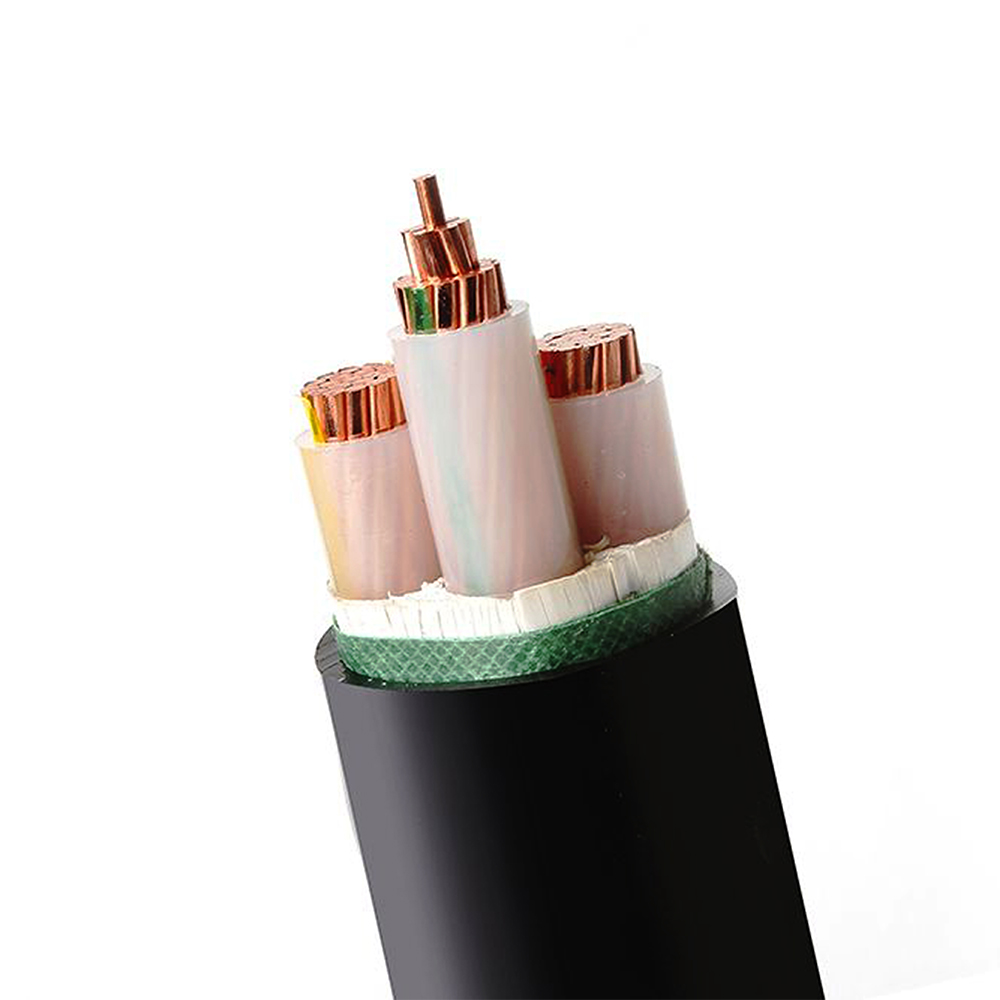
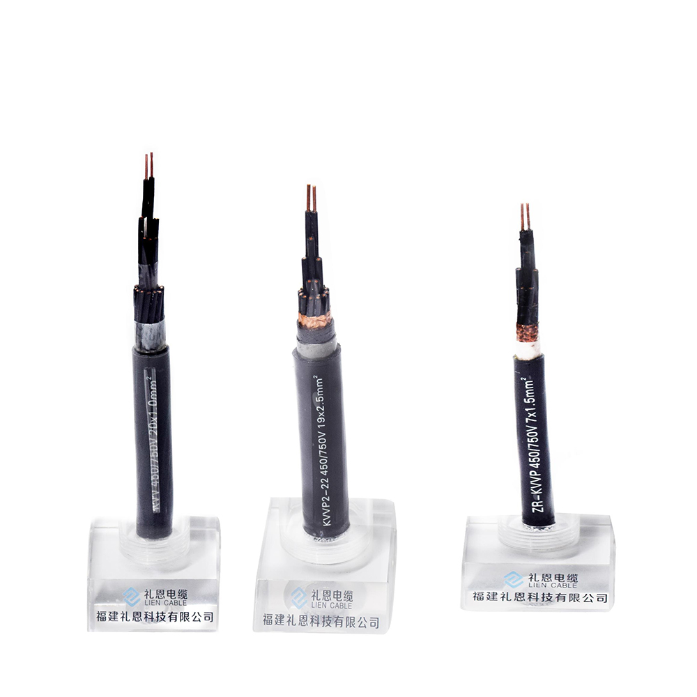
Control cable, insulated by PVC,XLPO/XLPE or PTFE material, is applicable for controlling and protecting circuits of rated voltage up to and including 450/750 V, used in enterprises of industrial and mining and department of energy source and transportation. It belongs to electrical equipments use cable which transmits electrical power from power system to various electrical equipments and tools.
Product specification
l Conductor type: stranded 99.95% OFC(oxygen free copper)
l Material :environmental friendly, fire resistant, flame retardant, low smoke halogen free, heat resistant
l Control cable color: black or other customized color
l Packing: carton packing, pallet packing, wooden steel drum or other packing method as requirements.
Three Main Type of our Control Cable
l PVC Insulated sheathed control cable
l Fire resistant control cable(PTFE)
l Radiation XLPO insulated control cable


Using features
*Rated power-frequency rated voltage U0/U is 450/750V
*Max. permissible continuous operating temperature of conductor:
l PVC Insulation type: 0℃
l XLPE Insulation type: 90℃
l PTFE Insulation type: 40℃~200℃
l XLPO Insulation type: 125℃
*The ambient temperature under installation should not be lower than 0℃, if the ambient temperature is below 0℃,the cable should be preheated.
Standard
This cable is manufactured according to GB/T9330-2008 standard. It can also be manufactured according to other standards upon request.
Application
Industrial and mining enterprises: iron and steel, coal manufacturing, etc
Modern high-rise building
Connecting line of electrical instruments and automation devices
For laying indoors, in trenches and in ducts, the cable should be shielded and for fixed installation.
Notes for installation
1. Don`t directly expose to the sunlight or superheat.
2. Don`t forget to check dry and wet level for installations in trenches regularly.
We can manufacture control cables as customer`s requirements. Welcome to contact us for more details about products and price. If later you want to visit our factory to get close to our production line, please also feel free to get in touch with us.
Control Cable
Control Cable,PVC Control Cable,Multicore Control Cable,Throttle Control Cable
Smartell Technology Co.,Ltd , http://www.liencable.com