Most of the high-fidelity speakers are composed of two or more speaker units. To restore the high-frequency audio signals from 20Hz to 20kHz, you must use the help of high-quality crossovers. Since the speaker units of the respective speakers are different, the frequency divider cannot be simply replaced, and must be made according to the characteristics of the specific speaker unit. Summarize a set of more complete design, production, debugging methods, only require the producer to have a "Hugo Gold Disc" containing 20Hz ~ 20kHz pure audio test signal, a microphone signal amplifier circuit, a microphone and a number A multimeter does not require a dedicated test instrument.
For amateur speakers, it is recommended to choose a two-way method.
First, the frequency of the crossover frequency f is selected. The crossover point of the two-way speaker can be optimized between 2 and 5 kHz. Generally, the frequency of the crossover point f is selected below the octave from the upper limit of the woofer, and the tweeter is within a range of the octave or more from the lower limit.
Second, the divider and power distribution constitute the high and low-range units of the speaker, the respective nominal power is not the same, and in the power spectrum of the actual program signal, the ratio of the high-frequency and low-frequency signals is also different, so After averaging the various signals, the analog signal power spectrum shown in Fig. 1 is obtained. The power spectrum of Figure 1 is calculated to obtain the power distribution curve shown in Figure 2. When selecting the crossover point, it is necessary to consider the power distribution problem, leaving a certain margin for the tweeter. Fig. 2 shows that the total power of 20 Hz to 20 kHz is normalized to 100%, and the power occupied by 20 Hz to a certain frequency f is a percentage of the total power. The application examples are as follows.
For example, a two-way system with a frequency division point of 2î€5kHz, from the horizontal coordinate of Fig. 2 to 2曲线5kHz to the curve intersecting, and the percentage read from the ordinate, the power ratio of 20Hz to 2.5kHz is 87%, 2î€5kHz The power ratio of ~20 kHz is 13%. When the total power is 100 W, the bass power W is low = 100 × 87% = 87 W, and the high power W is high = 100 × 13% = 13 W.
When using the power distribution relationship above, also pay attention to the power standard of the speaker unit. General product labeling is the rated maximum sinusoidal power (RMS), while some manufacturers label peak power or music power for commercial purposes, but the value is typically 2 to 4 times the RMS power.
Third, the frequency division method of the choice of frequency division method has 6dB / oct type, 18dB / oct type, 3dB landing point cross type and 12dB / oct type, 6dB landing point cross type, etc., but consider their advantages and disadvantages, A 12dB/oct type is recommended.
Fourth, when the crossover network design crossover network, such as adding the load unit to the RC impedance compensation circuit, as a constant impedance design, this is of course the best. However, after reviewing a large number of books and periodicals, the author found that there are many calculation methods for the RC impedance compensation circuit, and the RC values ​​obtained are not the same. It is difficult to select, and the design is based on the frequency point resistance method.
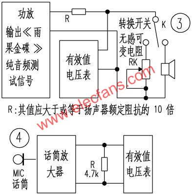
First, use the circuit connection shown in Figure 3 to measure the resistance of the high and low woofer units at the crossover point (be careful not to replace the unit's nominal impedance, otherwise the error will be large, then perform the calculation in the upper right table and press the graph. The LC components are connected, and the preliminary production is completed. The sensitivity of the high and low-wool units is unbalanced, and the resistance attenuation can be adjusted (in 1997, there is a special article in the electronic newspaper, No. 15). It is recommended to use high-quality polypropylene capacitors for optimization. The hollow core inductor is designed, and the components are fixed on the printed board with hot melt adhesive. The inductor can be reinforced by cotton or plastic zipper tape, and connected by scaffolding to make separate and separate sound lines of high and low sound channels. the way.
This article refers to the address: http://
V. Debugging method According to the inverse square law of sound pressure level, the point sound source is in free space, the distance is doubled, and the sound pressure level is attenuated by 6dB. By using this law, the following practical operations can be performed.
Install the speaker body and speaker unit, do not connect the crossover, use the "Hugo Gold Disc" test signal, according to the normal playback mode, with a fixed volume of 2 ~ 3W, repeat the frequency of the crossover point f, with the map 4 self-made simple sound pressure tester, test the sound pressure at 2m, adjust the microphone volume potentiometer to make the digital multimeter read, an easy-to-remember integer, write down the spare. Then, access the crossover low-pass network, put the sound pressure meter at 1m, the test reading should be the same as the last time, otherwise, increase (reduce) the capacitance according to the reading large (small) until the reading is the same (this The time division frequency f is attenuated by 6 dB). Then, the signal is directly input into the woofer unit, the test signal is adjusted to an octave signal higher than the frequency f of the crossover point, the sound pressure is tested at 4 m with a sound pressure meter, and the reading is recorded. Finally, access the crossover low-pass network, put the sound pressure meter at 1m, the reading is the same as the last time, otherwise, slightly fine-tuned (the octave frequency f is attenuated by 12dB), so that the bass network is debugged. . Repeat the above steps in the treble network to adjust the inductance. Note that the second step is to input the octave signal below the frequency f of the crossover point. In this way, a set of high quality crossovers is created and debugged.
LED Trunk Downligh, 7W, 12W, 14W, 21W, 24W, 36W for option. Multiple choice for beam angles, to reach the appropriate illumination angle.15°, 24°, 36° for options. CREE COB chip from USA. Warm white, natural white, cool white for option. Energy-saving, green and environmental protection, no mercury, no UV, infrared or other deleterious output are the advantages of LED Trunk Downlight. LED adjustable trunk downlight are popular in the shopping market, bar, exhibition hall, art gallery, hotel etc.


Trunk Downlight
Trunk Downlight,Round Trunk Downlight,Gimbal Trunk Downlight,Trunk Lighting LED Downlight
SHENZHEN KEHEI LIGHTING TECHNOLOGY CO.LTD , http://www.keheiled.com