1. Continuous Execution vs. Pulse Execution
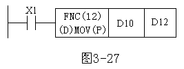
In PLC programming, function instructions are typically divided into two types: continuous execution and pulse execution. As shown in Figure 1, the instruction mnemonic "MOV" followed by a "P" indicates pulse execution, meaning that the instruction runs only once when X1 transitions from OFF to ON (i.e., sending data from D10 to D12). If there's no "P", it means the instruction is continuously executed every scan cycle while X1 is ON.

Figure 1 illustrates how function instructions execute and how data length is represented.
2. Data Length
Function instructions can process either 16-bit or 32-bit data. When the mnemonic includes a "D", it indicates that the instruction is designed for 32-bit data processing. Without the "D", it processes 16-bit data. It’s important to note that 32-bit counters (C200 to C255) are specifically 32-bit devices and cannot be used as operands for 16-bit instructions. For example, if the MOV instruction is preceded by a "D", then when X1 is turned on, D11D10 will be transferred to D13D12 (a 32-bit operation). When working with 32-bit data, it's recommended to use even-numbered addresses for the operands to avoid errors and ensure clarity in your program.
3.81mm Wire To Board Connectors
ShenZhen Antenk Electronics Co,Ltd , https://www.antenk.com