The scale remover introduced in this example uses the oxygen and hydrogen generated during the electrolysis of water to soften, loosen and fall off the scale, which is convenient to use and easy to operate.
Circuit Operation The scale remover circuit consists of a power supply circuit, a timer, a multivibrator, and a control execution circuit, as shown in Figure 3-211.
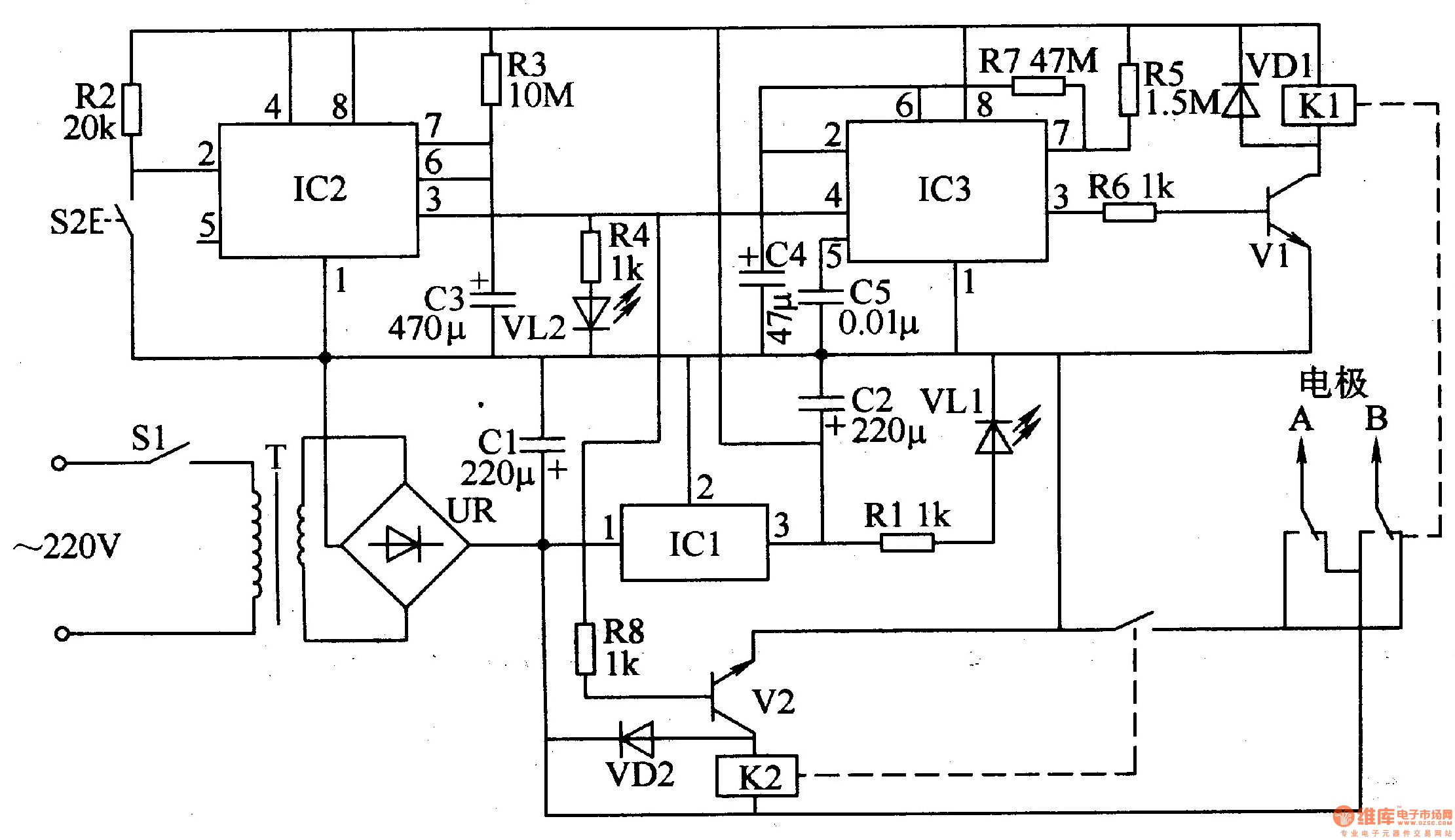
The power circuit is composed of a power transformer T, a rectifier bridge stack UR, a filter capacitor Cl, C2, a three-terminal integrated voltage regulator ICl, a current limiting resistor Rl, and a power indicating LED VLl.
The timer circuit is composed of a time base integrated circuit IC2, a start button S2, a resistor R2, a R3, a capacitor C3, a current limiting resistor R4, and a light emitting diode VL2.
The multivibrator circuit is composed of a time base integrated circuit IC3, resistors R5, R7, and capacitors C4, C5 and the like.
The control execution circuit is composed of transistors V1, V2 and relays K1, B, and the like.
When using the scale remover, the kettle should be filled with light salt water, then the electrode A should be connected to the metal shell of the kettle, and the electrode B (corrosion-resistant electrode such as carbon rod should be used) wrapped in gauze and placed in the kettle.
After the power switch S1 is turned on, the AC 220V voltage is subjected to T step-down, UR rectification, and Cl filtering to generate a DC 2OV voltage. In addition to supplying the relay K2, the voltage is further regulated to +l2V by ICl as the operating power source for IC2, 1C3 and Kl. After the power circuit is working, VLl lights up.
After pressing the start button S2, the timer circuit works, and the 3 pin of IC2 outputs a high level. On the one hand, V2 is turned on, K2 is connected, its normally open contact is turned on, and the DC 220V voltage passes through the K1 constant penalty contact. And the normally open contact of K2 is added to the two electrodes to electrolyze the water of the kettle; on the other hand, the multivibrator is oscillated (the oscillation frequency is determined by the capacity value of the capacitor C4), and the 3-pin output rectangle of the IC3 The wave oscillating signal, Vl is intermittently turned on, so that the relay K1 is synchronously coupled and released, and the polarity of the voltage on the two electrodes is switched. When the timer is working, the timing indicator LED VL2 is lit.
After the scale remover works for 9Omin, the timer stops working, IC3's 3 feet become low level, VL2 is extinguished, V2 is cut off, KZ is released (multi-vibrator also stops), the power of the two electrodes is cut off, and the descaling ends. .
Component selection
Rl-R8 uses 1/4W or 1/8W carbon film resistors.
Cl uses aluminum electrolytic capacitors with a withstand voltage of 25V; C2-C4 selects aluminum electrolytic capacitors with a withstand voltage of l6V; C5 uses polyester capacitors or monolithic capacitors.
Both VDl and VD2 use the lN4007 silicon rectifier diode.
VLl and V愧 select φ3mm LEDs.
UR uses 2A, 5OV rectifier bridge stack.
Vl and V2 select 2SC805O or C8050 silicon NPN transistor.
ICl selects LM7812 type three-terminal integrated voltage regulator; IC2 and 1C3 select NE555 type time base integrated circuit.
Kl selects l2V DC relay; K2 selects 2OV DC relay.
The electrode A can use a fresh fish clip; the electrode B can be made using a motor brush or a carbon rod of a dry battery.
REMOTE CONTROL SOCKET
Important Safeguards
When using any electrical appliance, in order to reduce the risk of fire, electric shock and/or injury to persons, basic safety precautions should always be follow8d. including:
• The appliance is for household and indoor use only.
• Before plugging in. check that the voitage on the rating label is the same as the mains supply.
• To protect against electric shock, do not immerse any part of the product in water or other liquid.
• This socket is intended for use by competent adults only and children should be supervised at all times.
• Do not use the socket for other than its intended use.
• This socket can be used by children aged from 8 years arxl above and persons with reduced physical, sensory or mental capabilities or lack of experience and knowledge if they have been given supervision or instruction concerning use of the appliance in a safe way and understand the hazards involved. Children shall not p<ay with the appliance Cleaning and user maintenance shall M be made by children without supervision.
• Children of less than 3 years should be kept away unless continuously supervised.
Children from 3 years and less than 8 years shall only switch on/off the appliance provided that it has been placed or installed in its intended normal operating position and they have been supervision or instruction concerning use of the appliance in a safe way and understand the hazards involved. Children aged from 3 years and less than 8 years shall not plug in. regulate and clean the appliance or perform user maintenance.
• Don't use this socket in the immediate surroundings of a bath, a shower or a swimming pool.
• In case of malfunction, do not try to repair the socket yourself, it may result in a fire hazard or electric shock
Do Not Exceed Maximum a680W
Place the LR44 batteries provided into the compartment in the back of the Remote Control, please insert as sho*/m in the back of the compartment to ensure the polarity is correct.
Programming Instructions
• Plug the Remoce Socket$($)lnto the wall socket(s) and switch on the mams supply, the red LED will flash every second.
• If the LED is not flashing press & hold the manual ON/OFF button for 5 seconds until it Hashes
•Press any ON switch on the Remote Control for approximately 2 seconds and the Remote Socket(s) learn the code. The LED will stop flashing top confirm the codehas been accepted.
• Any number of Remote Sockets can be programmed to one Remote Control ON button to create multiple switching.
• To programme o<her Remote Sockets on different Remote Control ON buttons repeat the prevous steps
• If the mains supply is turned off the Remote Sockets v/ill lose their code and it wil be necessary to re-pcogramme.
Operation:
• Plug your appliance(s) into the Remote Socket(s)
• Press the programmed ON or OFF button on the Remote Control to control the Remote Socket.
♦ The Remote Sockets can also be operated manually using its ON/OFF Button Trouble shooting
If a Remote Socket does not react to the Remote Control please check the followng:
♦ Low battery in tbo Remote Control
• Distance too large between the remote control and the recerver (ensure the range distance is no more than 20 clear Metres) and free from obstacle that may reduce the distance.
• If programming has not been successful, tum the power off and back on then follow the programming steps above.
How to decode
• Press the manual ONX)FF button for 5 seconds until the red LED flashes once per
second to confirm de-coding is successful
♦ Press the ALL OFF switch on the Remote Control for more than 3 seconds, the LED
flashes once per second to confirm (decoding successful.
Voltage: 240V-/50HZ
Max power rating: 3680W max.
Remote frequency:
Remote range:
Battery Type:
433.92MHz
230 Metres
Button Cell 2x1.5V LR44 =
Please check with your local waste management service authority regarding regulations for the safe disposal of the batteries. The batteries should never be placed G municipal waste.
Use a battery d^posal facility if available
M
For eioctncal products sold within the European Community. At the end of the electrical products useful life, it should not be disposed of wth household waste. Please recycle faaMies exist. Check with your Local Authonty or retailer for recycling advice.
C€
Remote Control Electrical Outlets,Remote Control Outlet,Remote Controlled Power Socket,Wireless Remote Control Outlet,Mini Wireless Remote Control Outlet,Wireless Remote Power Switch
NINGBO COWELL ELECTRONICS & TECHNOLOGY CO., LTD , https://www.cowellsockets.com