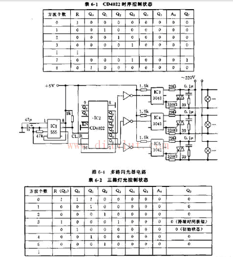
The circuit of the multi-channel flasher is shown in Figure 6-4. It can make several lights controlled by it flash in sequence, and the flashing cycle can be continuously adjusted. It can control up to eight lights and can be used for home, store and entertainment. Location lighting decoration.
Circuit principle: The circuit is output by IC1555 in 47UF capacitor. The working principle of CD4022 is: when the EN pin is grounded, the CL pin inputs the square wave pulse, and the R pin is at zero level, the initial output of the chip is set to Q7Q6Q5Q4Q3Q2Q1Q0=0 0 0 0 0 0 0 1, the output will change with the square wave pulse as shown in Table 6-1.
The eight outputs are sequentially high, each output is high, and the duration is one pulse period. Due to the zero-eliminating end of R, if any of the square waves arrives, if R=1, the output will immediately return to the service state. According to this feature, we connect the Q3 output to the R pin, and the CD4022 output will change with the input pulse according to Table 6-2.
The 2D Scanner adopts a unique split body in appearance design, with a large scanning window, it can easily meet various scanning needs. The three-stage adjustable configuration optimizes the scanner illumination, plus a unique one-key switching scanning mobile phone The QR code design makes it have superior 2D barcode scanning performance and mobile tolerance, and can easily scan QR codes on mobile phones.
Desktop Barcode Scanner ,Code Two Qr Code Desktop Reader,Desktop Qr Code Reader,Qr Code Scanner Desktop
ShengXiaoBang(GZ) Material Union Technology Co.Ltd , https://www.sxbgz.com