1 Introduction
In a recent experimental study, a new method for detecting engine operating conditions, ion current detection, has received close attention from researchers at home and abroad. When the engine is in the working chamber, the gas density is different due to different working conditions, and the magnitude and variation of the ion current through the spark plug are also different. Therefore, the spark plug electrode can be used as the signal sensor to detect various engine signals. The ion current detection method has two major advantages: firstly, it is easy to install, and the spark plug is used as the sensor directly. The structure is simple and the engine structure is not damaged. The test principle is relatively simple, the circuit is easy to implement, and can be used in engineering measurement; secondly, the price is lower. Can be used in a wide range.
The ignition test system described in this paper is mainly to simulate the operation of a four-cylinder engine. The MCU sends four pulse signals with a phase difference of 90 degrees to simulate, and the duty cycle of the pulse signal can be adjusted in real time according to the ignition energy. The ion current detecting part mainly extracts the ion current signal generated by the spark plug and performs amplification processing to detect the high voltage isolation. The biggest feature of the detector is that it can be easily detected without the need for special sensors.
2. Engine ignition system and ion current detection circuit
2.1 How the ignition system works
Figure 2-1 shows the equivalent circuit diagram of the primary circuit, consisting of the power supply (battery), the resistor, the primary winding of the ignition coil, the contacts and the capacitor. The specific working process is: when the contact is closed, the primary current passes through the power supply, and the additional resistance flows through the primary winding of the ignition coil. The primary current increases in an exponential manner, and the primary current has a limit value. The limit value is approximately UB/R. While the primary current is increasing, a self-induced potential is generated in the primary winding, and the secondary winding generates a potential corresponding to a magnitude of 1.5 kV to 2 kV, but this potential is insufficient to break the gap of the spark plug.

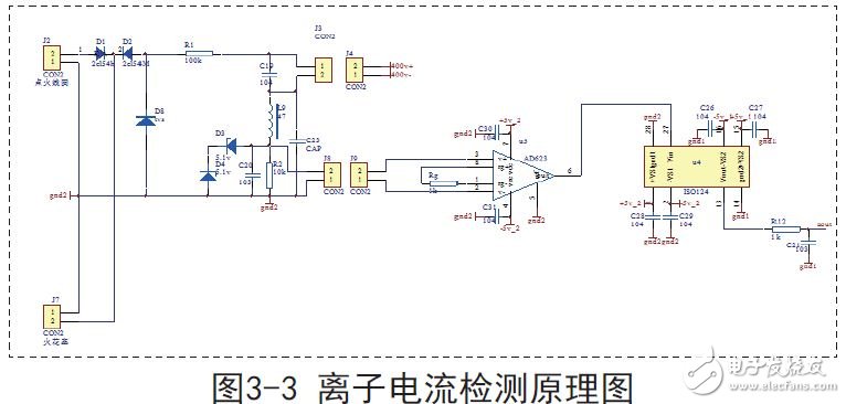
2.2 Principle of ion current electrical measurement
The ion current detection method is a method for analyzing and detecting the ion current generated between the two electrodes of the spark plug in the combustion chamber of the engine according to the applied bias voltage, thereby knowing the operation state of the engine. Since the spark plug ion current signal contains a lot of information about engine operation and combustion, we can extract the engine operating parameters that we need by collecting and processing the ion current signal to ensure that the engine is always in the optimal operating state. Using these operating parameters, we can also complete real-time monitoring of the engine's operating status, while processing the feedback information to complete the corresponding control, as well as fault detection of the engine.
3. Design and implementation of engine ion current detector
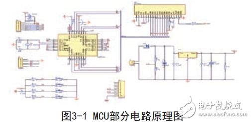
3.1 MCU control part circuit design
The moving circuit part amplifies the pulse signal from the MCU and directly connects with the ignition coil. In addition, a protection circuit is provided to feed back the signal to the MCU to protect the entire test system. Optocoupler is used for opto-isolation between the two parts. The schematic design of the MCU as a whole is shown in Figure 3-1, and the crystal oscillator is 12M.
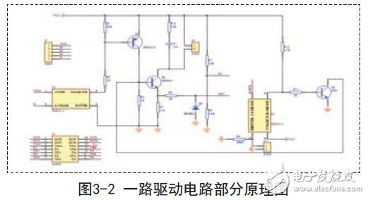
3.2 drive part circuit design
In order to make the whole ignition test system safe and reliable, the MCU part and the drive part are respectively designed into two PCB boards. The MCU completes the control display function, and the drive part is connected with the ignition coil, and controls the charging and discharging of the ignition coil according to the control signal sent by the MCU. The two parts are separated by a photocoupler. The design of one drive circuit is shown in Figure 3-2.
Spin dryers are very common in every family. Banshen spin dryers, with high quality, good design and best service. Many products have been sold to over 30 countries. After many years of developing, banshen spin dryers are getting better and better.
Our well-equipped facilities and excellent quality control throughout all stages of production enable us to guarantee total customer satisfaction. Besides, we have received CE, CB, RoHS and CCC certifications.
As a result of our high quality products and outstanding customer service, we have gained a global sales network reaching America, Asia, Europe, Africa, the Middle East and other countries and regions.
If you are interested in any of our products or would like to discuss a custom order, please feel free to contact us. We are looking forward to forming successful business relationships with new clients around the world in the near future.
Spin Dryer,Portable Spin Dryer,Spin Dryer For Clothes,Washing Machine With Dryer
Ningbo Banshen Electric Appliance Co., Ltd , https://www.banshendq.com