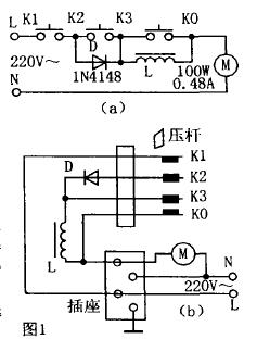
Micro motor foot speed governor is often used in small winding machines, sewing machines, copying machines, etc., as a step governor. The speed-regulating motor is generally a single-phase series-excited micro-motor with a power of 100W and a current of 0.48A. The electrical schematic of such a pedal governor is shown in Figure 1a. The wiring diagram is shown in Figure 1b. The working principle is as follows: when the pedal is pressed to make K1 and K2 are connected, the 220V mains is connected in series with the micro-motor M through the diode D and the reactor L, and the voltage obtained by the micro-motor is half due to the unidirectional conduction of the diode. The average value of the wave (L DC voltage drop is a few volts) is about 95V, and the micromotor is in a low speed operation state: when the pedal pressure lever causes K1, K2, and K3 to be simultaneously turned on, D is short-circuited by K2 and K3, 220V city. The electric motor is stepped down on the micro motor after being stepped down, and the micro motor is in the medium speed running state; when the foot pressing lever makes K1, K2, K3, and K0 all connected, the 220V main power is directly added to the micro motor. The micromotor runs at full speed, when the torque is maximum. In normal times, the micro-motor starts more frequently, and the pedal governor is subjected to a large current, which often causes the governor contacts to melt, stick and damage. And cause micro-motor brushes, armatures and other damage, causing a lot of inconvenience to the user.
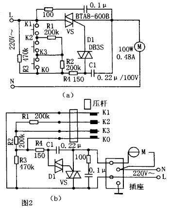
The improved pedal governor circuit schematic is shown in Figure 2a. The wiring diagram is shown in Figure 2b. The improved pedal governor adopts a two-way thyristor AC technology to control the conduction angle of the triac by changing the RC phase shift time constant to adjust the voltage applied to the micromotor to adjust the micromotor. The purpose of the speed. The improved governor uses the turn-on and turn-off of the original K1, K2, and K3 to adjust the RC time constant. Therefore, K1, K2, and K3 are subjected to a small current, which can greatly extend the service life of the contacts and improve the reliability and service life of the governor. The improved governor still adopts low-speed, medium-speed and full-speed step-by-step speed regulation, which is easy to manufacture, cost-saving, reliable in performance and long in service life.
working principle:
When K1, K2, and K3 are in the off state, the RC phase shifting circuit cannot make the VS trigger conduction because the resistance of R3 is large. When the pedal is pressed down to make K1 and K2 turn on, R1 and R2 are connected to the circuit, and the RC time constant is formed to make the triac turn on at a small conduction angle state, so that the micromotor runs at a low speed. Adjusting R1 gives a suitable low speed. When the pedal presses the K1, K2, and K3, R1 is short-circuited, R=(R2//R3)+R4, the RC time constant is in a moderate state, and the triac conduction angle is also in a moderate state. The motor runs at medium speed and adjusts R2 to get the required medium speed. When the pedal presses the K1, K2, K3, and K0, R1 and R2 are short-circuited. At this time, R=R4, the RC time constant is the smallest, and the micro-motor runs at full speed. Therefore, the foot pressure lever adjusts the on/off of K1, K2, and K3, and the micro motor can be adjusted to perform three speed speed adjustment operations of low speed, medium speed, and full speed.
The improved governor adopts a typical inductive load bidirectional thyristor speed control circuit, which can effectively prevent the influence of the inductance characteristics of the micro motor on the operational reliability of the triac speed control circuit. If you need to change to continuous stepless speed regulation, simply replace R1 and R2 with a 470kΩ potentiometer. In addition, the pedal presser is changed to a sawtooth strut that can drive the gear to rotate, so as to drive the potentiometer to rotate and adjust the RC time constant to achieve the purpose of continuous speed regulation.
Selection of components:
D1 selects the bidirectional trigger diode such as DB3S: VS selects the plastic bidirectional thyristor such as BTA8-600B with 600V and 8A current. Due to fewer components, the components can be fixed with insulating brackets.