Introduction USB (Universal Serial Bus) is a new type of data communication technology. When the USB interface is used to connect the device to the computer, there is no need to reset the system, and the cabinet does not need to be opened to adjust the finger switch of the interface card. The computer will automatically recognize the interface device and simultaneously transmit the driver to the peripheral device. The USB interface has the advantages of plug-and-play, fast speed, and easy expansion. It has become one of the most important interfaces on today's personal computers, and is an indispensable interface for general consumer electronic products.
Short-range wireless communication has the characteristics of strong anti-interference ability, high reliability, good security, less limited geographical conditions, simple and flexible installation and construction, and is widely used, such as car remote control key, wireless meter reading, wireless ordering, Remote telemetry, cell automation, etc. The maturity of multimedia has greatly promoted the integration of the above two technologies. Especially for audio signals, the USB sound card is far away from the high-frequency interference environment, and the sound quality is good and easy to carry. However, due to the influence of the audio interface line, the USB sound card is limited to a certain range, and cannot be used. At the same time, it is shared with many people, and the short-range wireless communication technology has the advantages of limited geographical conditions, high reliability, and good security.
Combining the advantages of both technologies, this design utilizes TI's PCM2702 to achieve USB audio signal acquisition, and uses Rohm's BH1417 to achieve stereo wireless transmission of audio signals. The frequency can be synchronously displayed by the single-chip microcomputer, and the switching of the frequency of the 14-segment frequency of 80-180 MHz can be controlled, and high-speed audio signal transmission within 10 to 100 m can be realized.
This article refers to the address: http://
1 main chip introduction
1.1 PCM2702 chip digital / analog conversion chip PCM2702 has two digital / analog conversion output channels and an integrated USB interface controller, the interface is in line with the USB1.0 standard; using the newly developed SPAct (adaptive period sampling The control tracking system is capable of separating a stable, less skewed clock signal from the audio data of the USB interface to coordinate the operation of the PLL and DAC.
The PCM2702 is mainly composed of three parts: an enhanced multi-level δ-sigma modulator developed by Burr-Brown, an 8× resampled digital interpolation filter and an analog output low-pass filter. The PCM2702 accepts 16-bit stereo or mono audio data at 48 kHz, 44 kHz, and 32 kHz; it integrates a software mute function with a digital potentiometer that controls potentiometer and mute functions via USB audio level requirements.
1.2 BH1417 chip BH1417 is a large-scale dedicated FM transmitter integrated circuit integrating stereo FM, frequency synthesis and RF amplifier. It operates in the 87-108 MHz band and works with simple peripheral circuitry to transmit audio FM signals for wireless FM stereo transmission with a conventional FM stereo receiver. The stereo signal transmitted by the FM stereo transmitter has a signal separation of 50 dB, distortion of less than 0.3%, and the stability of the circuit is greatly enhanced. In terms of sending and receiving effects, it is almost close to a regular FM station.
BH1417 consists of 5 parts: audio pre-processing circuit (emphasis, limiting and low-pass filtering); base frequency generating circuit (crystal oscillator, frequency division); phase-locked loop circuit (phase detection, frequency-locking); frequency setting circuit (high and low) Level shifting); FM transmitting circuit. The peripheral circuits mainly include a frequency control circuit, a carrier generation circuit composed of a voltage controlled oscillator, a timer, and some coupling capacitors.
The BH1417 integrates the pre-emphasis circuit, the limiter circuit, and the low-pass filter circuit (LPF) to make the quality of the audio signal much better than that of the discrete components (such as BA1404, NJM2035, etc.); the phase-locked loop is used to lock the frequency, and Integrated with the FM transmitter circuit, the frequency of the transmission is very stable; using 4 high and low levels for frequency setting, 14 frequency points can be set, which is very convenient to use.
2 hardware circuit design The schematic diagram of USB audio transmission system is shown in Figure 1. The system is mainly composed of a USB sound card module, a wireless transmitting module, a single chip control module, a keyboard input module, a frequency display module and a power module.
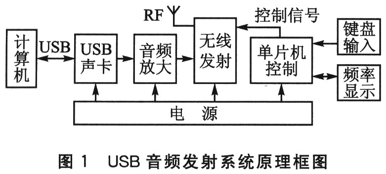
When the USB sound card module is connected to the computer, the computer automatically recognizes and outputs a stereo audio signal; the audio signal is transmitted to the wireless transmitting module, and after being processed, converted into a frequency modulated wave and transmitted. At the same time, the MCU system will control the high and low levels of the four pins D0~D3 of the FM transmitter module, thereby controlling the transmission frequency and synchronously displaying the transmission frequency.
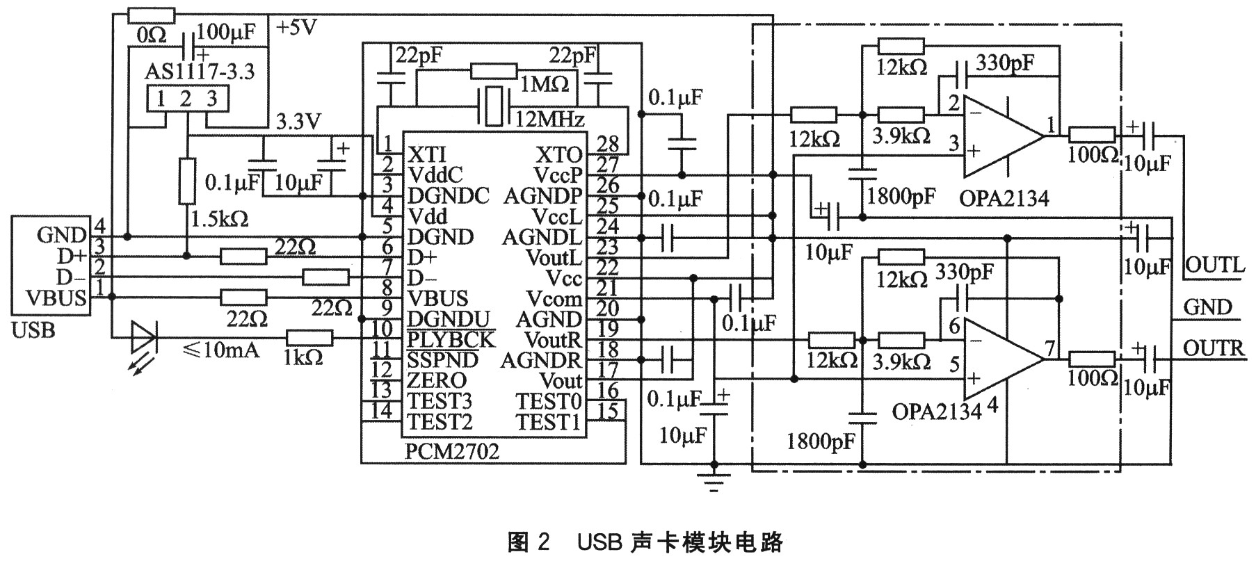
2.1 USB sound card module As shown in Figure 2, the USB sound card module is mainly composed of a 16-bit stereo digital-to-analog conversion chip PCM2702 with a USB interface and an audio operational amplifier OPA2134. The peripheral circuit of PCM2702 is relatively simple. It is powered by digital/analog dual power supply. When the digital-to-analog signal is grounded, it is isolated by magnetic beads or O Ω resistors, which effectively reduces the interference between digital-to-analog signals. At the analog output end of the PCM2702, considering the insufficient driving capability of the signal, the audio dedicated op amp OPA2134 is used to form a multi-feedback low-pass filter, and the signal is further amplified and restored, and the output audio signal is directly used by the wireless transmitting module. Considering the effect of the overall sound quality, the capacitance associated with the audio signal in the circuit should be as high as possible.
2.2 Wireless Transmitter Module As shown in Figure 3, the wireless transmitter module is mainly composed of a large-scale dedicated FM transmitter integrated circuit BH1417 and a simple peripheral circuit.
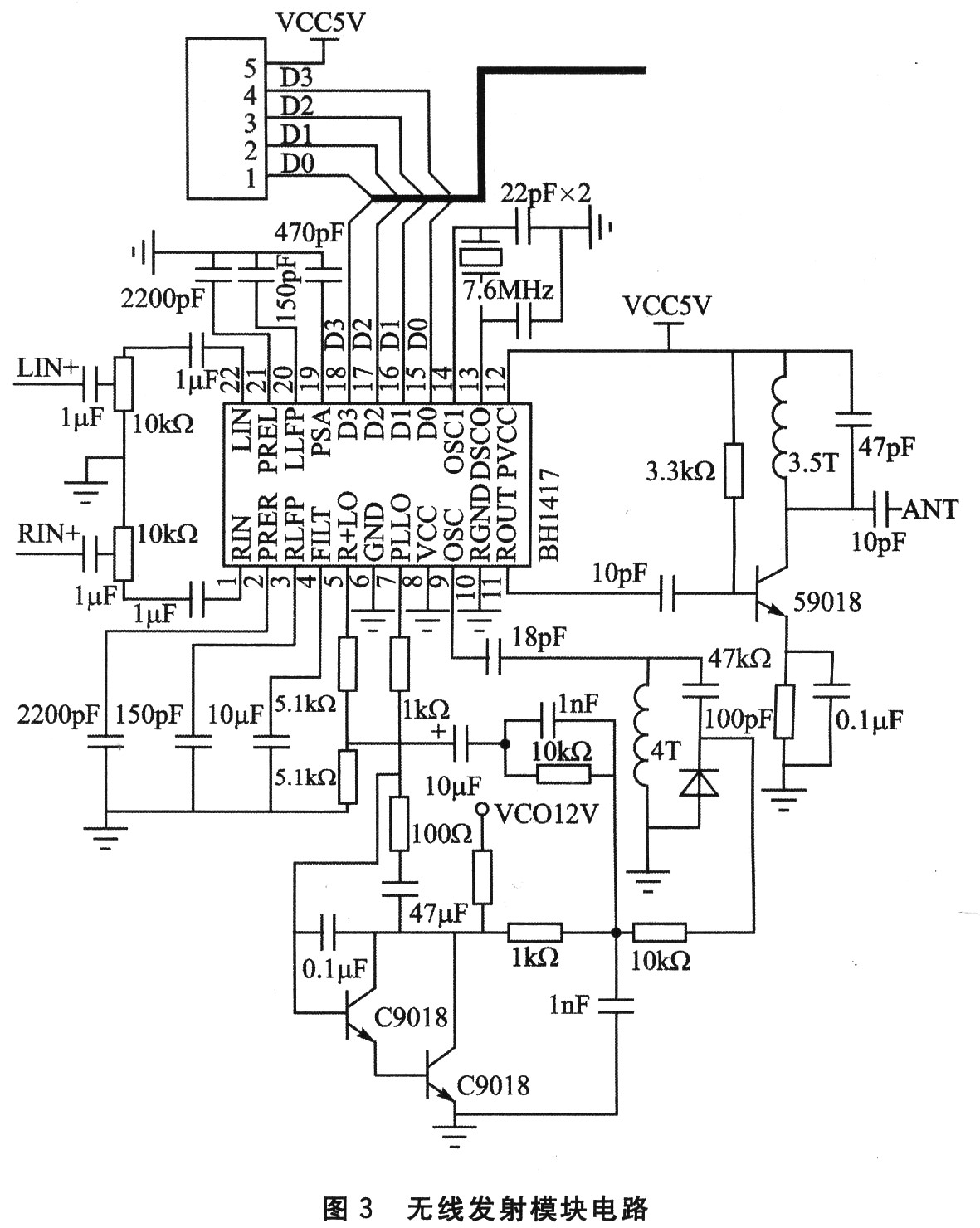
(1) Stereo modulation circuit After the audio signal is input through pins 1 and 22, the 21, 20, 19, 2, 3, 4 pins of the BH1417 and the external circuit are matched by the pre-emphasis circuit, the limiter circuit and the low-pass filter. Send to the mixer. An oscillating circuit with a 7.6 MHz crystal input from pins 13 and 14 generates a subcarrier signal of 38 kHz by dividing by 200. The 38 kHz subcarrier is divided by 2 to generate a pilot signal of 19 kHz, the left channel minus the right channel signal is balanced with the 38 kHz subcarrier, and the modulated composite signal is output through the 5 pin.
(2) FM transmission circuit The FM transmission circuit uses a frequency-stabilized phase-locked loop system. After the frequency code input to the 15, 16th, 17th, and 18th pins of the BH1417 is decoded and phase-detected, the control signal VCO of the LC oscillator is output from the 7-pin. The VCO controls the high-frequency oscillating circuit composed of the external discrete components to generate the FM-modulated carrier signal, and performs FM frequency modulation on the composite stereo signal outputted by the 5-pin through two triodes C9018. The modulated signal is input to the BH1417 through the 9-pin, and the RF signal amplified by the internal RF amplifier is output from the 11-pin. The output signal can be directly connected to the transmitting antenna for transmission. The corresponding high and low levels of the BH1417 frequency point emission are listed in Table 1.

(3) The 5, 7, 9, 10, 12 pins of the high-frequency oscillating circuit BH1417 are matched with the discrete components connected thereto to form the frequency oscillation and RF modulation part of the FM carrier; the pins 13 and 14 require an external 7.6 MHz crystal. The oscillator provides a stable clock required for phase discrimination and stereo signal modulation inside the BH1417; 6, 8 is the power supply part; and the 11-pin externally connected component constitutes the FM signal transmission part.
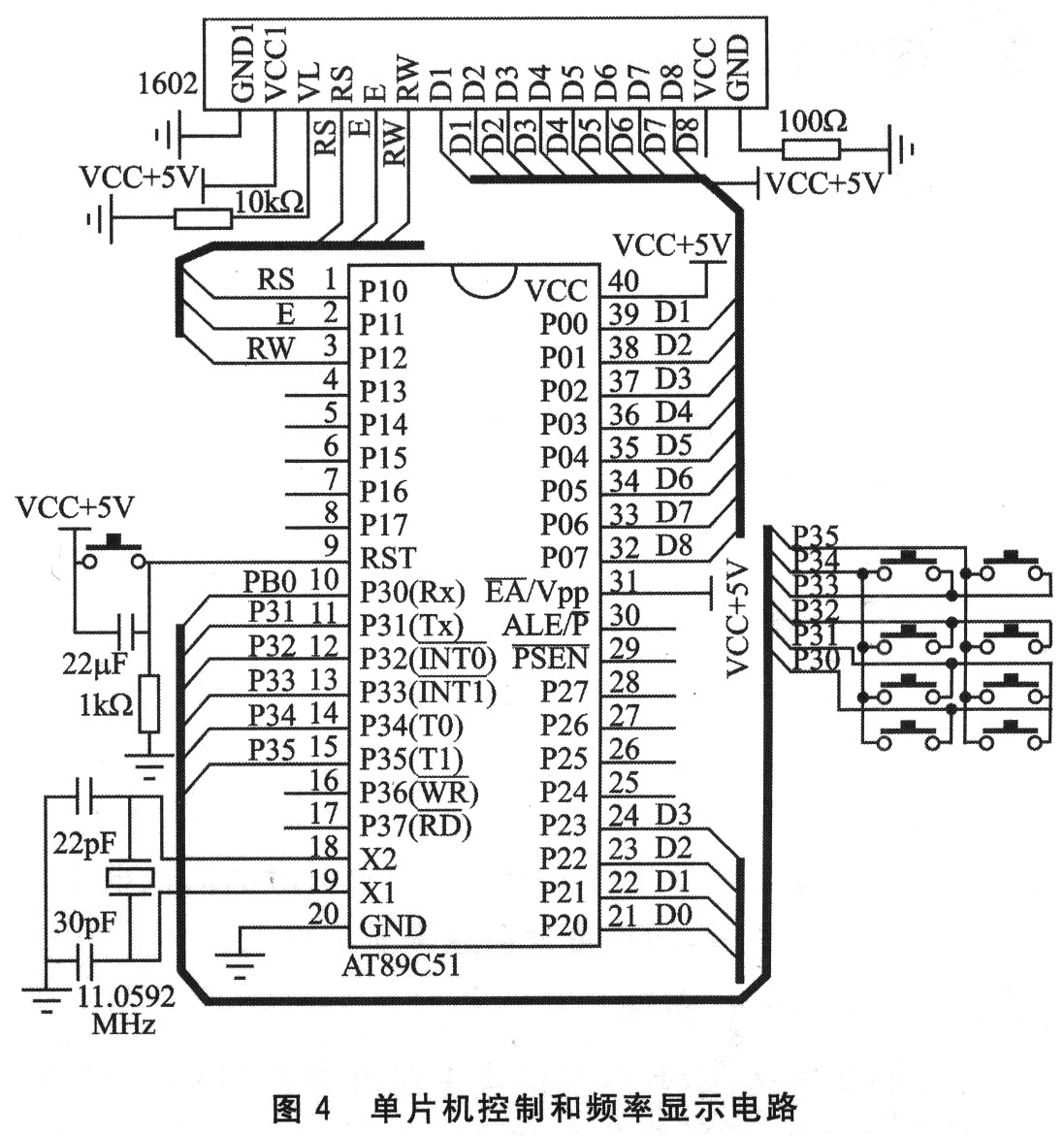
(4) Transistor amplifying circuit After the 11-pin signal of the BH1417 is output, the 9018 is used for one-stage amplification. 2.3 MCU control and frequency display module MCU control and frequency display circuit shown in Figure 4, mainly composed of AT89C51, keyboard input and liquid crystal display module. The four pins of the P2 port of the MCU are respectively connected to the 15, 16, 17, and 18 pins of the BH1417, and the high and low levels are controlled by the keyboard, thereby controlling the frequency output of the BH1417, and simultaneously displaying the frequency to the 1602 liquid crystal.
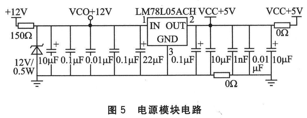
2.4 Power Module The power module circuit is shown in Figure 5. The 12 V DC input passes through the LM78L05ACH regulator and has a 5 V output. The power supply section mainly provides power for USB sound card analog output, audio amplification, wireless transmission, and microcontroller control and frequency display. In order to reduce the interference of the wireless transmitter module to the microcontroller control and the frequency display module, a magnetic bead or a 0 Ω resistor can be added between the power supply and the ground.
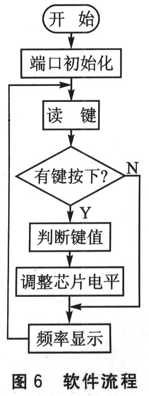
3 software programming system software process shown in Figure 6. After the system is powered on, the MCU system is initialized. The four ports of P2 are all low, set to 87.7 MHz transmission, and the frequency is displayed on 1602. Then enter the keyboard cycle scan state, when the keyboard is detected to determine the key value, according to the key value to adjust the level of the P2 four ports, and then control the BH1417's transmission frequency, and then display the frequency. The operating frequency of this system is divided into 14 frequency bands, as shown in Table 1. Determine the key value to increase/decrease the frequency. When the frequency reaches 88.9 MHz or 106.7 MHz, the PLL stop gear is skipped.
4 System production, debugging and anti-interference measures In the welding of the system, pay attention to the welding of the patch to prevent the static electricity of the human body and the soldering iron from damaging the chip. Since the system is a signal transmission, the length of the signal line should be minimized when laying on a general-purpose board, and the filter capacitor should be as close as possible to the output component to avoid generating extra clutter.
During the system debugging process, due to the digital circuit, analog low frequency and analog high frequency circuit in the system, pay attention to the correct connection of the relevant power supply, so as to avoid abnormality and interference of the circuit, and decoupling circuit should be added between the power supplies. First debug the USB sound card module. According to the PCM2702, the USB power-on time is short to ensure that the computer finds the device correctly and installs it. Then, the debugging of the wireless transmitting module is performed. Since the laboratory does not have a frequency measuring instrument, it has to directly receive the test directly with a highly accurate radio. When testing, first connect the four control pins with a jumper to ensure that the wireless signal can be transmitted, then the frequency correction and the MCU control display.
The system has certain requirements for anti-interference, so digital, analog low-frequency, analog high-frequency power ports are respectively provided in the power module, and magnetic beads and O Ω resistors are added to reduce mutual interference. In the circuit design, each module is independently formed into blocks, grounded around to reduce electromagnetic interference, etc.; and necessary protection circuits are added to each module to ensure the stability and reliability of the circuit.
Conclusion The USB audio transmission system based on PCM2702 and BH1417 adopts a modular design method, which makes the whole system have certain scalability and can be used separately and independently. Although there is also a USB sound card and an infinite USB sound card solution composed of 2.4 GHz, due to its variable frequency and the need for a matching receiving device, it cannot be shared with many people and the confidentiality is not strong. With FM transmission, you can use the off-the-shelf radio to receive, and the frequency can be adjusted to enhance security.
6028 SMD LED,SMD LED Chip ,SMD LED Types ,SMD LED Diode
LED Bulb Light Co., Ltd. , http://www.nbsmdled.com