ZigBee wireless sensor ECG monitor technology
This paper designs a home telemedicine monitor based on the ZigBee wireless sensor network. The integrated LCD support provided by the LPC2478 based on the ARM7 core displays the image, and the signal is stored on the SD card and transmitted to the 10/100 Ethernet Hospital, hospital feedback information and display it on the LCD, and the coordinator gateway of the community clinic wirelessly returns the diagnosis result to the corresponding family and displays it on the family LCD. The user can transmit the result to the home computer for storage. This design can easily construct a health detection network, and can get a doctor's diagnosis without complicated operations, which is very suitable for home users.
System implementation
The sensors in this system are used to detect the weak signals of the electrocardiogram, and then encoded after amplification and filtering, and then sent to the gateway based on the ARM and ZigBee coordinator module through the ZigBee wireless module, and sent to the host computer for display processing through the peripheral interface Then, it is transmitted to the community clinic via Ethernet, and the clinic returns each person's information to their respective families through the ZigBee wireless module, and displays the hospital's feedback of the processing information on the LCD. Reasonable chip selection can achieve low power consumption, low cost, and detect weak ECG waveform changes.
Technical characteristics
1. With LPC2478, a variety of high-bandwidth peripherals can be synchronized for information processing and real-time display.
2. Adopt CC2430-based ZigBee wireless transmission, low cost, low power consumption, strong self-organizing network capability, reliable transmission, small size and easy to carry.
3. The community clinic can store the diagnosis results of the owners of the entire community, and can provide necessary reminders and preventions for the diagnosis results of each owner, effectively reducing the incidence rate.
4. The user can store the diagnosis results on the home computer for easy backup.
Hardware platform
The hardware part of the embedded wireless sensor ECG monitor mainly includes master control, power supply and reset, LCD display, ZigBee coordinator, ZigBee router, ZigBee endpoint, sensor and amplification filter conditioning circuit, SD card storage, 10/100 Ethernet, etc. 9 functional modules. The hardware design block diagram is shown in Figure 1.
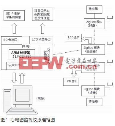
Main control module
The module uses the LPC2478 microcontroller based on the ARM7TDMI-S core, which is powerful and cost-effective, contains an LCD controller, supports 10/100 Ethernet, full speed (12Mbps) USB2.0, USB OTG and 2 CAN2. 0B channel, 4 UARTs, 1 SPI interface, 2 synchronous serial interfaces (SSP), 3 I2C and 1 I2S interfaces, with on-chip high-speed 512KB Flash, 98kB RAM, an external memory interface, 10-bit A / D and D / A converter, an internal RC oscillator and an SD memory card interface, thus eliminating the communication bandwidth bottleneck, easy to expand the USB interface, JTAG debugging interface, touch screen, less external expansion chip, and the use of ultra-small LQFP208 package makes the miniaturization of the instrument guaranteed, and its powerful functions can meet the requirements of embedded system mC / OS-II and humanized human-machine interface. LPC2478 is very suitable for portable electronic product applications.
ZigBee module
The ZigBee radio frequency (RF) front end, memory and microcontroller are integrated on the CC2430 chip. Its enhanced 8051MCU core performance is 8 times the performance of the industry standard 8051 microcontroller core; it has 32/64/128 kB programmable flash memory and 8 kB of RAM; also contains 8 input channels, 8 to 14 bit selectable analog-to-digital converters (ADC), 4 timers; with 2 powerful USARTs that support several sets of protocols; wider voltage range ( 2.0 ~ 3.6 V); hardware supports CSMA / CA function; current consumption is only 0.9mA in sleep mode, external interrupt or RTC can wake up the system, current consumption is less than 0.6mA in standby mode, external interrupt can wake up the system; integrated 2.4GHz RF radio transceiver conforming to IEEE802.15.4 standard; has excellent radio receiving sensitivity and strong anti-interference; high integration, less peripheral devices required; expansion board contains serial port and LCD display, etc. for data string Line transmission and data display. Signal acquisition and conditioning
The AD620, a low-power, high-precision instrumentation amplifier, is used as the core device of the preamplifier. AD620 has the characteristics of high precision, high input impedance, low input bias current, low input offset current, low noise, low power consumption, small size, etc. It is very suitable for application in medical instrument systems. The low-pass filter circuit uses Butterworth fourth-order filter TLC04, which is low-cost, easy to use, and provides precise fourth-order low-pass filter functions. The buffer is an in-phase voltage follower, its role is to improve the system input impedance and common mode rejection ratio. The wave limiter uses a double-T band stop filter to filter out the 50 Hz power frequency interference. The main amplifier uses a full power output amplitude four operational amplifier TLC2274, which provides excellent AC performance, and provides lower noise, lower input offset voltage and lower power consumption than ordinary CMOS op amps.
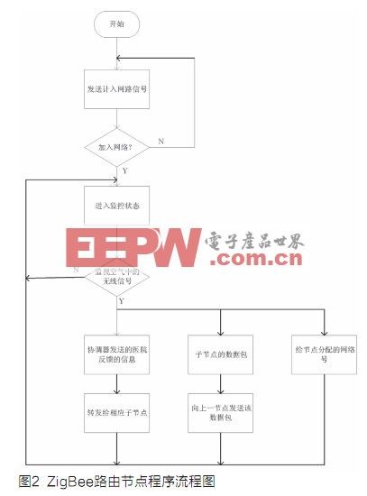
The program flow chart of ZigBee routing node is shown in Figure 2.
Data processing and display description
This design uses the differential threshold method to detect QRS waves. The basic idea is: perform differential operation on the filtered ECG signal, find the differential threshold to determine the falling edge of the QRS waveform, and then determine the QRS according to a certain time window and amplitude threshold The characteristic points of the wave.
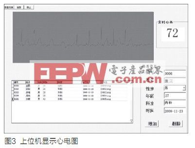
The main principle of scanning electrocardiography is to draw points from left to right, and display the corresponding positions in sequence. At the same time, the new points cover the original points, and there is a buffer zone in the middle to erase the old points. When drawing to the far right, draw the next picture from the far left, and repeat it all the way. The upper computer displays the waveform as shown in Figure 3.
Headlight is Powerful light at the front of a vehicle. One motorcycle usually needs a one or two bulbs. It is depend on the original lamp design. Driver need power light to illuminate the road in front of them to keep them safe, so the halogen bulbs are usually been used as headlight. Halogen bulb can generate more light and has better working life hours. The supply voltage of halogen lamp is usually divided into 6V, 12V and 24V. The halogen lamp is made of tungsten, but it is enclosed in a smaller quartz glass shell. Normally, the halogen bulb will create ultraviolet when light, so we must use quartz coating to prevent head lamp been damaged by the ultraviolet generated by halogen bulb. To generate more light, the filament be heated to the very high temperature, so halogen bulb is hotter than a normal bulb.
Headlight Bulbs,LED Headlight Bulbs,Dual Color Yellow Lamp,Fog Light
Heshan Jianhao Lighting Industrial Co., Ltd. , https://www.sunclubtw.com