Introduction The personal position tracking system described in this article is the application of radio frequency identification system (RFID) in personal positioning, that is, a system that uses wireless links to achieve personal position positioning. The frequency of the system is 433MHz and the communication distance is 200 meters. The system is divided into handheld stations, base stations and information processing databases. The basic principle is that the synchronous clock signal is transmitted by the time-transmitting base station. After receiving the signal, the handheld station exchanges data with the receiving base station in a certain order. After exchanging the data information, the base station updates the database in real time, and it is displayed by the management PC. It can alarm when needed.
Air Link Arrangement Generally, before designing a wireless receiving system, a demonstration of link budget analysis must be performed. Through the demonstration, it can be predicted that under certain output bit error rate (BER) and signal-to-noise ratio (SNR), in order to meet the design requirements, the receiver needs noise figure (NF), gain, and transmitter output power. According to the theory of radio frequency, the free space loss of the signal:
L (dBm) = 20log (4R /) = 20log (4Rf / c)
In the formula: R is the communication distance; f is the signal frequency; c is the speed of light.
When f is in MHz and R is in km, you can get:
L (dBm) = 32.45 + 20logf (MHz) + 20logR (km)
If 433MHz is used as the air link frequency, then L (dBm) = 85.2 + 20logR (km).
The corresponding value list is shown in Table 1.
Since the communication distance is set to 200 meters, the aerial dynamics are 1 meter to 200 meters, that is, the dynamic range is 71.2-25.2 = 46dB. Considering the attenuation of 30dB in different directions of the body, the dynamic range reaches 46 + 30 = 76dB. Of course, the actual signal often has more than free space loss during the propagation process, and there are other losses, which will make the air link worse. Generally, these losses can be compensated by increasing the transmission power, reducing the receiving NF, increasing the receiving gain, and increasing the gain of the transmitting and receiving antennas.
The circuit of the handheld station is composed of two parts: the first part is a single-chip microcomputer, whose main function is to control the RF module and save the information related to the handheld station ID. The radio frequency module is responsible for receiving and transmitting the signal sent by the base station MCU. Since the handheld station is powered by batteries, power consumption, receiving sensitivity, and low operating voltage are important indicators.
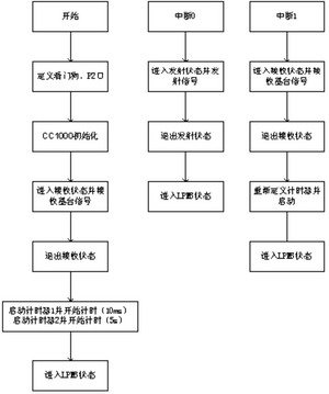
Figure 1 Software flow chart of the handheld station
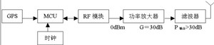
Figure 2 Block diagram of complex time transmitting base station circuit
The important parameters of the handheld station are:
The circuit of the handheld station can be composed of the single-chip RF transceiver chip CC1000 of CHIPCON and the MSP430F1121 microprocessor of TI. CC1000 is a low power consumption, low operating voltage, single chip UHF wireless transceiver chip. The chip is mainly designed for small-scale, short-range communication in industrial production, technology, and medical applications. The frequency generally works at 315, 433, 868, and 915MHz, but the parameters required for the chip to operate at any frequency within 300 ~ 1000MHz can be easily calculated by special software, and can be coordinated with various microprocessors. Define its working status quickly and easily. The MSP430F1121 microprocessor is also a powerful one-chip computer with ultra-low power consumption. It has multiple working modes, the working current is 0.1 to 400uA depending on the working mode. An interrupt can wake up the system from various operating modes. The RETI instruction returns the MSP430 to the working mode before the interrupt event. Therefore, it is possible to save energy consumption for the handheld station. In addition, the MSP430 microprocessor can complete the setting of various working states of CC1000, which is convenient and fast. The circuit formed by these two ICs can fully meet the technical specifications of the handheld station as follows:
The software flow chart of the handheld station is shown in Figure 1.
The basic characteristics and software and hardware design of the base station are as follows:
The main function of the time-transmitting base station is to be responsible for sending a synchronized clock signal to each handheld station at regular intervals. After the handheld station receives the signal, it starts to use the timer to start timing. The timing of different handheld stations can be staggered by modifying the program, and then enters the sleep state, waiting for the interrupt to wake up.
Only one timing transmitter can be installed in an area. If multiple stations are needed, GPS timing is required. According to the needs of the system, the working distance of the timing transmitter is 1km, and the path loss is 85.2dB, the receiving sensitivity is -96dBm, and the protection energy of 30dB, then the energy required by the receiver is -96 + 33 =- 66dBm. If the antenna of the timing transmitter is omnidirectional, G = 30dB, then the power of the transmitter should be greater than (-66 + 85.2) dBm = 19.2dBm.
Designed according to the transmission power of 1W, the circuit block diagram of the designed timing transmission base station is shown in 2.
The main function of the receiving base station is to be responsible for receiving the data information sent by each handheld device. And is responsible for transmitting all data information to the management PC in time, and the management PC updates the database in real time according to these information. The receiving base station can be distributed at multiple points.
According to the system design requirements, the receiving distance is designed at 200m. The transmission power of the handheld station is 0dBm, plus a 40dB guard band, so the power received by the receiving station is: -71.2-40 = -111.2dBm.
If the antenna gain and transmission offset is 0dB, the receiving sensitivity is -111.2dBm, and the intermediate frequency bandwidth is set to 200kHz, then the lowest detectable input power level Pmin = -174 + 53 = -121dBm, then the front-end filter insertion loss L≤4dB, then NF must be <5dB, so the circuit block diagram is shown in Figure 3.
In addition, considering that at 0.001km, the air link attenuation is 25.2dB, so the maximum energy received by the receiving base station is -25.2dBm, from which the dynamics of the system is (-25.2 + 111.2) dB = 86dB.
In order to ensure a normal path, at the receiving base station, a low-noise amplifier LNA (G≥15dB, NF1≤2dB) needs to be added, and an automatic gain control circuit AGC with an adjustable attenuation of 20dB is required.
According to the needs of actual design, the front-end filter uses a surface acoustic wave filter with f = 433MHz, and its insertion loss L = 1.5dB. The noise figure of the passive lossy network is:
The noise figure of the system is:
1.41 + 0.36 + 0.38 = 2.16
Then: NF = 3.34dB <5dB, fully meet the requirements of system design.
The RF module of the base station also uses a single-chip RF transceiver chip CC1000. But in order to save costs, MCU can use 51 series single chip. Since the voltage of the CC1000 power supply is 3V, it is necessary to design a conversion circuit that converts from the 3V level to the 5V level. The conversion circuit can use a dedicated level conversion chip, such as Philips' 74LVC4245 and Maxim's MAX3370, and can also use the conversion circuit solution on the CHIPCON company's development board.
When the communication range is not very large, for example, within 200 meters, the timing transmitting base station and receiving base station can be combined into one. The software flow chart of the base station at this time is shown in Figure 4.
Power consumption analysis In the design of the system, the handheld battery uses the button battery as the system power supply method. Therefore, the power consumption of the handheld station is one of the key considerations in the design, which can be said to be the key to the success of this system. In order to clarify the problem of power consumption, the transmission process of basic air data needs to be analyzed first.
According to the needs of the system design, the scheduled transmission base station must make a scheduled transmission every 5s, and the capacity of the system is 256, using 19.2k baud rate to transmit data. The 136-bit timing code frame format is as follows.

Figure 3 Block diagram of the receiving base station circuit

Figure 4 Overall flow chart of base station software
Since the capacity of one frame of data is 136 bits in total, the time required for sending 136 & TImes; (1 / 19.2) & TImes; 10-3 = 7ms, so the total capacity in the interval of 5s is (5/7) × 103 = 714 Because the system design capacity is 256 bits, the system capacity is large enough.
After the hand-held station receives the timing signal sent by the time-transmitting base station, it delays 10ms before it starts to send data to the receiving base station one after another. After the data is sent, it enters the sleep state and reduces the power consumption. After receiving the data from all the handheld stations, the receiving base station updates the database in real time and displays the results or alarms.
The interval of the transmission timing sequence is 5s, of which 7ms is used for transmission (10.4mA); the other 7ms is used for reception (7.4mA). A handset will take 14ms.
Therefore, the total power consumption of the handheld station is:
720 × 7 × (10.4 + 7.4) /3600000=0.02492 mA / hour
The 900mA / hour battery can be used for 4.1 years. Of course, with the power consumption of the MCU, the battery life will be reduced.
Conclusion The main functions and parameters of the personal location tracking system and its solution introduced in this article have basically met the system requirements. However, there is room for improvement in software, especially in error correction coding.
Test Dc Power Supply,Anodizinf Power Supply,Electroplating Dc Power Supply,Dual Output Dc Power Supply
Yangzhou IdealTek Electronics Co., Ltd. , https://www.idealtekpower.com