I. Introduction
Semiconductor lighting is a rising star in lighting systems. It has long life, environmental protection, energy saving, pure light color, safety and reliability. With the further deepening of semiconductor theory research and the continuous advancement of semiconductor technology, human beings have more and more confidence in using LED as a future light source. LED has gradually replaced electric light sources such as incandescent lamps and fluorescent lamps, and has become a mainstream product of artificial light sources.
With the widespread use of high-power LEDs in lighting decoration and lighting, the driving circuit of power LEDs is becoming more and more important. Without a good driver to match the LED, the advantages of LED lighting are difficult to reflect. High-power LED driver integrated circuits are indispensable key components in LED lighting systems. Therefore, integrated circuits play a vital role in whether LEDs can achieve energy saving, solid color, and environmental protection.
Adopting the "constant current drive" method is an ideal LED driving method, which can avoid the current fluctuation caused by the change of the LED forward voltage, and the constant current stabilizes the brightness of the LED. Therefore, most power LEDs use the "constant current drive" method.
In the conventional LED drive circuit, a constant voltage drive mode is often used. However, due to the difference in semiconductor manufacturing processes, batches and batches, wafers and wafers, and chips and chips are inevitably subject to some small differences, resulting in uneven brightness of the LEDs and even burning of the chips. Therefore, application engineers have to worry about circuit design. Even if the circuit design is complicated, some unexpected things will inevitably occur. The reason is due to the difference in the forward voltage of the LED. Because in the LED string and combined connection mode, the current on the LED is different under the same voltage, so that the LED that flows through the large current emits strong light, and the small light is weak, resulting in the LED with strong illumination first. burn.
Since the LED is a current-driven device, it can illuminate stably if it gives the LED a stable current. Therefore, the constant current drive circuit shows its unique performance when the constant voltage drive is at a loss. Below, we will take XLT604 as an example to discuss the characteristics of the constant current drive circuit in detail, introduce the design and application of the circuit, and give some reference circuits.
Second, XLT604 special circuit design example
1. Function introduction
The XLT604 is a PWM high efficiency LED dc drive control chip designed in BICMOS technology. The input voltage Vin ranges from 8VDC to 450VDC and provides constant current drive for high-brightness LEDs. The operating frequency of the chip is determined by an external resistor. The frequency up to 300KHz is used to drive the external MOSFET. The LED string is controlled by constant current to maintain constant brightness and enhance the reliability of the LED. The constant current value is measured by the external sampling resistor. The decision ranged from a few milliamps to l amps.
The LEI) driven by the XLT6O4 can adjust the brightness linearly through an external control voltage, or the brightness of the LED string can be adjusted by an external low-frequency PWM method.
2. System function block diagram (Figure 1)
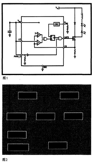
3. Chip internal module and block diagram
The XLT604 chip includes reference power, RC oscillation, power-on reset, linear dimming, PWM dimming, low voltage detection, and control logic. Output driver and other modules. The reference power module generates the reference voltage and the reference current inside the chip; the pulse signal generated by the RC oscillator module is used to control the on and off of the external switch tube, the frequency of which can be adjusted by an external resistor, and the linear dimming module passes the given voltage and the feedback voltage. The comparison determines the on/off of the switch tube; the PWM dimming module adjusts the on/off of the switch tube by externally giving the duty cycle of the PWM signal; the low voltage detection module determines whether the chip operates by monitoring the value of the power supply voltage. (Figure 2)
Third, XLT604 application circuit
1. Typical application diagram
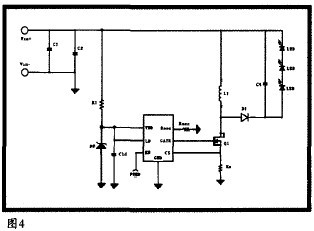
(1) AC-DC step-down application (Figure 3)
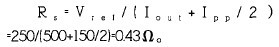
(2) DC-DC step-down application (Figure 4)
2. Application principle analysis
(1) AC-DC application
The XLT604 is a control chip that can step down, boost, and buck-boost high-power LED strings. The chip is suitable for both AC input and 8-450VDC input. In the case of AC input, a passive power factor correction circuit can be added to the line to increase the power factor. The XLT604 can drive hundreds or thousands of LEDs in series or in series, ensuring LED brightness and extending life by adjusting the constant current value. The PWMD terminal can adjust the brightness of the LED by the method of low-frequency pulse width modulation, and also serves as the enable end. When the terminal is suspended, the chip has no output control. The chip can also adjust the brightness of the LED by linearly regulating the LD terminal.
(2) LED drive control
The XLT604 can control converters including isolated/non-isolated, continuous/discontinuous, and the like. When the GATE terminal outputs a high level, the energy stored in the inductor or the primary side of the transformer or part of the energy is directly transmitted to the LED string. When the power MOSFET is turned off, the energy stored in the inductor is converted into the driving current of the LED.
When the VDD voltage is greater than UVLO, the GATE terminal can output a high level, which works by limiting the current peak of the power transistor. The external current sampling resistor is connected in series with the source of the power tube. When the voltage value of the external sampling resistor Rs exceeds the set value (the internal setting value is 250mV, which can also be set externally by the LD), the power tube is turned off. If you want the system to soft start, you can connect a capacitor Cld (Cld in Figure 3) to the ground at the LD terminal to increase the voltage at the LD terminal at the desired rate, thus controlling the LED current to rise slowly.
(3) Sampling resistance value
For a buck topology, the peak voltage at the CS terminal can represent the average current of the LED, but there is some error compared to the average. Assume that the peak current value Ipp on the inductor is 150 mA, and the reference Vid set at the LD terminal is 250 mV. To obtain the LD current Iout of 500 mA, the sampling resistor can be determined by the following method:
(4) Dimming
There are two ways to dim: linear adjustment, PWM adjustment. The two methods can be adjusted individually or in combination.
Linear dimming is achieved by adjusting the LD terminal voltage from 0 to 250 mV, which is prior to the internal set point of 250 mV. The voltage at the CS terminal can be changed by adjusting the varistor connected to GND. When the voltage at the LD terminal is higher than 250mV, the output current will not be affected. If you want a larger output current, you can choose a smaller sampling resistor Rs (ie, the smaller the Rs, the larger the output current).
PWM dimming is achieved by adding a PWM signal of several hundred Hz to the PWMD terminal. At this time, the brightness of the LED lamp is proportional to the high-level time length of the PWM signal. In this mode, the LED current is one of O or a set value. The PWM adjustment method can be used to dim the O-100% range, but the current higher than the set value cannot be adjusted. The PWM dimming accuracy is limited only by the narrowest pulse width of the GATE output.
(5) Oscillation frequency
The internal oscillation frequency of the chip is adjusted by an external resistor Rosc, and its frequency range is from 25KHz to 3OCKHz. The oscillation frequency can be calculated by the following formula:
Fcsc = 22000/(Rcsc[KΩ]+22)[KHz] (constants 22000 and 22 are determined when designing the internal oscillating circuit and are inherent parameters of the internal RC oscillation)
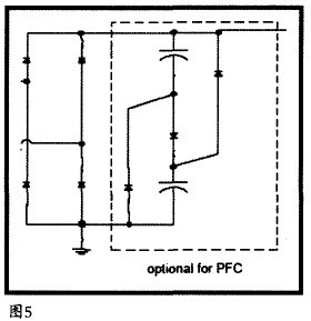
(6) Power factor correction
When the power input power does not exceed 25W, a simple passive power factor correction circuit can be used. The circuit consists of three diodes and two capacitors, which can increase the circuit power factor to 85%. The PFC circuit is shown in dotted line in Figure 5:
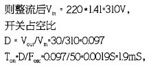
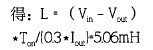
(7)Buck topology
Set the input voltage AC effective value to 220V, Iout=350mA, Fosc= 50KHz, the forward voltage drop of lO LEDs: Vout = 30V; then the rectified Vtn=220*1.4l=3l0V,
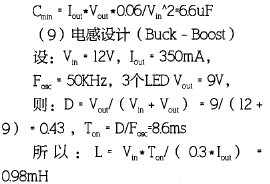
(8) Input filter capacitor
The input filter capacitor value should ensure that the rectified voltage value is always greater than twice the LED string voltage. Assuming a 15% ripple voltage across the capacitor, a simple calculation is as follows:
Fourth, the conclusion
By analyzing the characteristics of constant voltage output and constant current output LED driver circuit, this paper clarifies the advantages of constant current driver circuit in LED driver circuit, discusses the internal structure and design idea of ​​power LED driver chip and its application circuit design. The XLT604 circuit is used to realize high-power LEDs driven by the mains, which solves the problems of buck and constant current and energy conversion, and is also relatively high.
For example, the conversion efficiency, higher power factor, and smaller volume ensure high-power LD operation for a long time. The advantages of constant current driving LEDs and the key device parameters that need to be adjusted during circuit design are analyzed in detail. To provide some reference for the majority of application engineers, at the same time, also provide a choice of driver chips for LEDs widely used in street lamps, table lamps and other products.
Edit: Cedar
Washing machines are very common in every family. Banshen washing machines, with high quality, good design and best service. Many products have been sold to over 30 countries. After many years of developing, banshen washing machines are getting better and better.
Our well-equipped facilities and excellent quality control throughout all stages of production enable us to guarantee total customer satisfaction. Besides, we have received CE, CB, RoHS and CCC certifications.
As a result of our high quality products and outstanding customer service, we have gained a global sales network reaching America, Asia, Europe, Africa, the Middle East and other countries and regions.
If you are interested in any of our products or would like to discuss a custom order, please feel free to contact us. We are looking forward to forming successful business relationships with new clients around the world in the near future.
Portable Washer,Baby Washing Machine,Twin Tub Washing Machine,3Kg Portable Twin Tub Washing Machine
Ningbo Banshen Electric Appliance Co., Ltd , https://www.banshendq.com