Abstract: Digital audio power amplifiers are small in size, light in weight, and highly reliable, but they do not work ideally. In order to further improve the efficiency of digital power amplifier, the three-level natural sampling method (NBDD) pulse width modulation technology is introduced into the pulse width modulation design of digital power amplifier, and the Dead-Time technology is introduced into the design of switching amplifier. The optimized design of the digital audio power amplifier improves the distortion index of the whole machine, reduces the design order of the low-pass filter, and improves the signal-to-noise ratio.
Keywords: digital audio power amplifier; NBDD; Dead-Time; switching amplifier
This article refers to the address: http://
0 Introduction In recent years, with the manifestation of digital advantages, many areas that have not yet been digitized are gradually being added to the ranks of digitization. The digitized speech signal must be D/A converted before it reaches the analog power amplifier to be amplified by the power amplifier. Therefore, from the perspective of fully digitalization, the power amplifier digitization mode is imperative.
Power amplifiers are usually classified into five categories according to their working states: Class A, Class AB, Class B, Class C, and Class D. Among them, the first four categories can directly input the analog audio signal directly, and the signal is used to push the speaker to sound after amplification. Class D amplifiers are special. They have only two states, on and off. Therefore, they cannot directly input analog audio signals. Instead, they need to transform the signals and then amplify them.
The digital audio power amplification technology adopts a new amplification system. The power amplifier tube works in the D-type switch state. Compared with the traditional analog power amplifier, it has a small volume, high power, and seamlessly combined with the digital sound source, which can effectively reduce the transmission between signals. Interference, high fidelity and other advantages have broad prospects for development.
In this paper, an optimal design scheme for high-efficiency digital power amplifier is proposed. The double-band natural sampling method (NBDD) pulse width modulation technology is introduced into the pulse width modulation design of digital power amplifier, which reduces the design order of low-pass filter and improves the design. Signal-to-noise ratio; by introducing Dead-Time technology into the design of the switching amplifier, the crosstalk loss and drain-source capacitance loss of the switching amplifier are reduced.
1 Optimization scheme realization principle This scheme uses two independent channels, which can complete the digital processing and power amplification of signals separately and simultaneously, and can be bridged into one channel for digital processing and power amplification of signals. Each channel works in the half-bridge mode of operation and can be bridged into a full-bridge mode of operation. The implementation principle is shown in Figure 1.
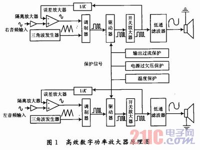
The input analog audio signal is first amplified by an isolation amplifier and low pass filtered. The low-pass filter uses a second-order Butterworth low-pass filter with a cutoff frequency of 37 kHz and a 3 dB bandwidth of 22 kHz. The filtered signal is sent to the error amplifier together with the feedback audio signal for error amplification, and the amplified error audio signal is output. The amplified error signal and carrier signal are sent to a pulse width modulator, and NBDD modulation is performed to generate a PWM signal. The carrier signal is a high linearity analog triangular wave signal generated by a triangular wave generator, and the frequency is adjustable from 230 to 280 kHz. After the PWM signal is inserted into the Dead-Time, it is sent to the driver of the floating Power Supply and the bootstrap for pre-amplification. The amplified PWM signal drives the half-bridge switching amplifier composed of the FET to perform power amplification and output power PWM signal. The PWM signal amplified by the switching amplifier is sampled as a feedback signal and sent to the error amplifier. The power PWM signal is sent to a low pass filter to restore the analog audio signal. When you need to bridge the single-channel output, you only need to send the equal-amplitude inverted audio signal at the input of the two bridges, and connect the load to the output of the two bridges. In order to increase the reliability of the module, the design also takes into account the damage caused by various misoperations, and provides a fault indication function to help the whole machine find the problem in time and facilitate the module for maintenance.
2 NBDD modulation technology implementation The specific implementation of NBDD modulation technology is shown in Figure 2.
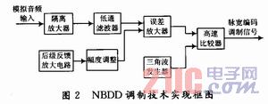
The input analog audio signal is first amplified by an isolation amplifier, and then sent to the error amplifier together with the feedback audio signal to output an amplified error audio signal. The amplified error signal and carrier signal are sent to a pulse width modulator for NBDD modulation. The carrier signal is a high linearity analog triangular wave signal generated by a triangular wave generator with a frequency of 230 to 280 kHz.
The focus here is on achieving high linearity triangular wave generators and high speed comparators. The nonlinearity of the triangular wave directly affects the linearity of the PWM modulator and the distortion of the whole machine. In order to restore the audio well, the PWM switching frequency cannot be lower than 200 kHz, so a high-speed comparator is required. The modulation method not only affects the performance specifications in the audio band, but also has a decisive influence on the high frequency radiation performance (EMC) of the amplifier system. Therefore, from the audio input to the pulse width coding completion link, the audio amplifier and error amplifier used should have high input impedance, low operating current, wide gain bandwidth, fast rising speed, good common mode rejection ratio, Low drift voltage and other technical indicators; the comparator should have fast response, low power consumption, and low input offset voltage.
3 Optimized design of switching amplifiers with Dead-Time The main feature of switching amplifiers is their high efficiency. Therefore, their optimized design should be mainly reflected in further reducing various types of losses and truly reflecting its high efficiency.
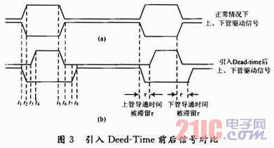
Through the principle of crosstalk loss, you can find a way to drive the gate drive voltage. After the upper tube is completely cut off, let the lower tube start to conduct. After the lower tube is completely cut off, let the upper tube start to conduct. This can reduce the collusion. Loss while reducing the junction capacitance Cds loss. In order to solve the crosstalk loss, the principle of "delay conduction, normal cutoff" between the two drive signals is called Dead-Time, and the principle is shown in FIG. The figure analyzes two N-channel field effect transistors operating on a switching arm.
4 Indicator Tests The indicator test mainly uses the audio precision tester Audio Precision System One, which is widely used internationally. Audio Precision System One is manufactured by Audio Precision, Inc., the world's largest manufacturer of audio test equipment.
The power supply is sent to the power socket of the sample to be tested via the ammeter; the voltmeter is connected in parallel between the positive and negative terminals of the power supply, and the voltmeter and ammeter are used to test the voltage and current of the power supply output, respectively, so that the power output power can be calculated. The audio input end of the sampled tester is connected to the audio output end of the audio tester, and the power audio output end is respectively connected to the audio tester and the standard power resistor, and the power signal outputted by the test sample is sent to the standard load and sent to the audio tester. Conduct analytical testing. The frequency and amplitude of the output signal of the audio tester Audio Precision System One are selected by the computer, and the indicators to be tested are selected, and the test results are displayed on the computer.
4.1 Function indicator test Connect the module as normal. If there is no special requirement for the sine wave with an audio input frequency of 1 kHz, the power supply voltage is ±120 V. Test socket XSZ 8 feet, if it is high level (+SV), it means the module is in protection state, the audio output pin has no signal output; if it is low level (OV), it means the module is in normal working state, the audio output pin has Signal output.
The test items and test conditions are:
(1) Silent control: input mute signal, no output of audio output pin, 8 feet of XSZ is high, the module is in protection state, respond to external mute control;
(2) Power supply overvoltage protection: increase the +120 V power supply to +128 V, the negative power supply remains unchanged, the module enters the protection state; the -120 V power supply is reduced to -128 V, the positive power supply remains unchanged, and the module enters protection. status;
(3) Power supply undervoltage protection: reduce the +120 V power supply to +100 V, the negative power supply remains unchanged, the module enters the protection state; the -120 V power supply is raised to -100 V, the positive power supply remains unchanged, and the module enters protection. status;
(4) Reverse connection protection of the power supply: the power supply is reversed and connected, and the module enters the protection state without damage;
(5) Power supply over-current protection: The output standard load is changed to 2 Ω, and the input audio signal amplitude is increased. When the output power exceeds 2 800 W, the audio output pin has no signal output, the XS2 8 pin is high, and the module is in protection state. ;
(6) High temperature protection: The module is heated by the high temperature thermostat. When the internal temperature of the module reaches +80 °C, the audio output pin has no signal output, the 8 pin of XS2 is high, and the module is in protection state;
(7) Output ground protection: short the module output audio pin to ground, no output of audio output pin, 8 feet of XS2 is high, the module is in protection state;
(8) Output short-circuit protection: short the module output audio pins, the audio output pin has no signal output, the XS2 8 pin is high, and the module is in protection state;
(9) Protection indication: When the module enters any protection state, the 8th pin of XS2 is high and the module is in protection state.
It can be seen from the above test results that the digital power amplifier can meet the requirements of stable operation in many aspects such as mute control, power supply overvoltage protection and power supply undervoltage protection.
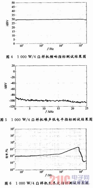
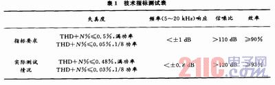
4.2 Technical Specifications Test The sine wave with an audio input frequency of 1 kHz has a supply voltage of ±120 V. Use computer control to select the audio tester Audio Precision System One settings, and select test items according to different indicators. The test results are shown in Table 1, Figure 4 to Figure 6.
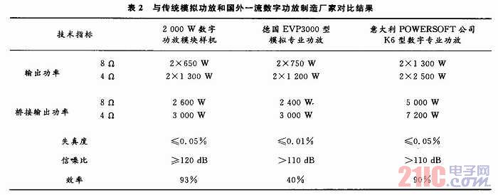
4.3 Analysis of test results The test indicators are compared with traditional analog power amplifiers and foreign first-class digital power amplifier manufacturers. The results are shown in Table 2. From the comparison results, it can be seen that the performance indicators of the prototype are basically consistent with the professional amplifiers of internationally renowned manufacturers.
The high-efficiency digital power amplifier optimization design scheme is reasonable and feasible through the research and development of the prototype, and achieves high efficiency and high index amplification of the audio signal. It has achieved ideal results in the development of high-power fields, and realized the NBDD pulse width modulation method. High-quality pulse width modulation, perfect reproduction of pulse width modulation waveform, high distortion index, various protection measures taken to improve system reliability have achieved the expected results, and improved system reliability.
5 Conclusion The NBDD modulation method is used to pulse-width modulate the audio signal. After adding Dead-Time, the pulse width modulation signal is amplified by the combination of floating power supply and bootstrap. The amplified pulse width modulation signal drives half. The switching amplifier in the bridge working mode performs power amplification, which realizes the optimized design of the high-efficiency digital audio power amplifier. The various optimization designs adopted in the scheme design have achieved certain effects, and the analysis and calculation methods are reasonable and feasible.
SMT Feeder , original and new or used one, in stock.
Material: Stainless steel
Feeder can be divided into tape feeder, tube feeder, tray feeder or stick feeder.
Feeder can be divided into original feeder and replacement feeder.
All the feeders shall be maintained during the use time
Yamaha Smt Feeder
Yamaha Feeder
Smt Feeder For Yamaha
Siemens Smt Feeder
Siemens Feeder
Samsung Smt Feeder
Smt Feeder
Smt Feeder,Smt Tape Feeder,Feeder For Smt Machine,Smt Machine Feeder
Shenzhen Srisung Technology Co.,Limited , http://www.sr-smt.com