With TMS320F28335 DSP as the core controller, the design scheme of three-phase 8-pole brushless DC motor control system is proposed. The main hardware circuit and software program have been designed in detail, and the corresponding circuit schematic and program flow chart are given. The speed adjustment algorithm adopts the improved single neuron adaptive PID control algorithm, and adaptively adjusts the control parameters to improve the adaptability of the control system to the environment. The experimental results show that the designed brushless DC motor control system is feasible. The improved single-neuron adaptive PID control algorithm can make the response time of the brushless DC motor shorter, and the overshoot and fluctuation are smaller.
0 Preface
Brushless DC motors are the result of a combination of power electronics, microelectronics, control theory and motor technology. The utility model has the advantages of short starting time, large starting torque and braking torque, large speed regulation range, simple structure, low noise, high reliability and long maintenance period. It is widely used in defense, aerospace, robotics, self-balancing vehicles, drones, electric vehicles, household appliances, office automation, and industrial process control.
In this paper, the design scheme of the control system of brushless DC motor based on TMS320F28335 DSP is given. The main hardware circuit module of the control system is designed in detail, including the design of motor drive circuit and control circuit. The design method of the speed adjustment subroutine is given.
The speed adjustment algorithm usually adopts the traditional PID control algorithm, but its control parameters adopt a one-time setting method. In order to achieve good control effects in various operation stages, the determination of parameters is often difficult to achieve. Literature [3] proposed an immune feedback PID control based on fuzzy adjustment, which has the advantages of simple structure, high reliability and strong robustness of traditional PID control, which improves the anti-interference and adaptability to working conditions. 4] Combining particle swarm optimization algorithm with single neuron adaptive control, it is applied in the control system of brushless DC motor, which improves the adaptability of the system; the literature [5] combines genetic algorithm and fuzzy control to motor Optimized control, the control system's adaptability has been improved. In [6], the RBF neural network is used to optimize the brushless DC motor control system. The motor speed and phase current are sampled in real time, the weight vector of the neural network is corrected, and the motor speed is controlled by controlling the armature voltage.
In this paper, the improved single neuron adaptive PID control algorithm can adaptively adjust the control parameters to improve the system's adaptability to the environment. Experiments show that the improved single neuron adaptive PID control algorithm can make the response time of brushless DC motor shorter, and the overshoot and fluctuation are smaller.
1 system overall design
The TMS320F28335 DSP is used as the core control chip, and the brushless DC motor control system is designed. The DSP captures the hopping signal of the position sensor through the capture ports CAP1, CAP2, and CAP3, triggers the capture interrupt, and reads the level state of the three CAP ports to obtain the motor control word, and then the DSP issues a corresponding control command to change the PWM signal. The switching quantity, in turn, changes the conduction sequence of the switching tube to achieve control of the motor speed and the direction of rotation. The design block diagram of the control system is shown in Figure 1.
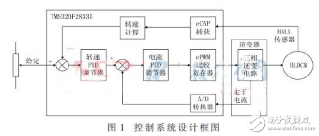
The control system is controlled by a 24 V/65 W three-phase 8-pole brushless DC motor. The speed and current double closed loop are used to control the speed of the motor. The outer loop of the system is a speed loop. The DSP obtains the current setpoint by improving the single neuron adaptive PID control algorithm according to the given speed value and the speed value obtained by the Hall sensor. The inner loop is a current loop. The output current of the speed controller is compared with the current value obtained by A/D sampling. The traditional PID control algorithm is used to give the corresponding PWM control signal to realize the speed control of the motor. .
2 hardware circuit design
2.1 Brushless DC motor drive circuit
The main function of the power conversion circuit is to invert the DC bus voltage to an AC voltage to drive the rotation of the brushless DC motor. The control object of this paper is 65 W small and medium-sized motor. Therefore, the power conversion circuit adopts the method of driving chip + MOSFE. The PWM signal output by DSP is sent to the driving chip after power amplification and photoelectric isolation processing, and the driving power transistor MOSFET is turned on and off. .
The driver chip selects IR2136 produced by InternaTIonal RecTIfier. This chip is a three-phase inverter circuit driver integrated circuit, which is suitable for driving brushless DC motor, permanent magnet synchronous and AC asynchronous motor. The circuit diagram of the driver chip is shown in Figure 2.
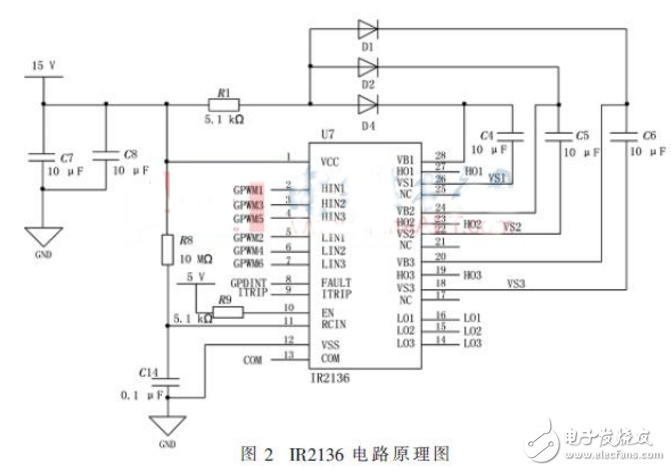
In Figure 2, diodes D1, D2, D4 and capacitors C4, C5, and C6 form a boost circuit. The function of the diode is to prevent current from flowing back. The function of the capacitor is to store the voltage. When the pulse frequency is high, the voltage of the booster circuit is the input voltage plus the capacitor storage voltage, resulting in an increase in voltage. The boost circuit is designed to increase the drive voltage amplitude so that the drive chip can reliably drive the high-side power tube to turn on.
2.2 Control circuit
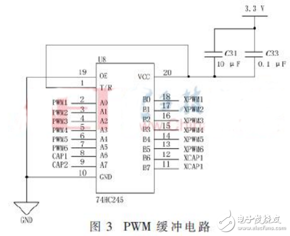
The ePWM module of TMS320F28335 has 6 sub-modules of ePWM1~ePWM6, and each ePWM sub-module has two PWM outputs, namely ePWMxA and ePWMxB. The three-phase current bridge consists of six power tube MOSFETs, and the control signals of the two power tube MOSFETs on each arm are correlated. Therefore, the first three ePWM sub-modules (ePWM1, ePWM2, ePWM3) can meet the control requirements of the brushless DC motor. The PWM control signals are ePWM1A and ePWM1B, ePWM2A and ePWM2B, ePWM3A and ePWM3B, respectively. Because the load capacity of the DSP pin output signal is limited, the output PWM signal needs to pass the power amplifier to improve the load capacity. The selected power amplifier is 74HC245, and the corresponding circuit is shown in Figure 3.
Portable Speaker,Loudest Bluetooth Speaker,Trolley Speaker For Sale,Rechargeable Trolley Speaker
Newmax Electronics Co.,LTD , https://www.fspeaker.com