1 Introduction
At present, the main development directions of the domestic and foreign password lock systems are: contact type password lock system, non-contact type password lock system, and intelligent identification code lock system; however, they all have different shortcomings. The cost of the infrared remote control code lock system is equivalent to that of the contact type lock system, and it can be remotely controlled and used very conveniently. The digital signal coding and the secondary modulation method can not only realize the control of multi-channel information, increase the remote control function, improve the anti-interference of signal transmission, reduce malfunction, and low power consumption; the infrared rays will not leak to the outside and will not be generated. Signal crosstalk; fast response, high transmission efficiency, stable and reliable operation. In industrial equipment, in the environment of high pressure, radiation, toxic gas, dust, etc., the use of infrared remote control is not only completely reliable but also effectively isolates electrical interference. Therefore, infrared remote control is currently the most widely used communication and remote control means.
To this end, the design of the scheme consists of a receiving part controlled by an infrared receiving head HS0038 (infrared receiving frequency of 38khz) and AT89C51; the transmitting part controlled by the infrared light emitting diode and the AT89C51 completes the password transmission process. Electromagnetic relays are used in the design to replace the functions, and there are two LED lights to indicate the system's buttons and unlocks. The application design of the remote control system using the single chip microcomputer has flexible programming and clear circuit structure. Especially suitable for families, hotels, warehouses, private garages and other places.
2. The overall design of the password lock
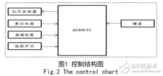
This system adopts AT89C51 single-chip microcomputer as the core component of this design. The system consists of two parts: the transmitting module and the receiving module. The remote control transmitting module can be carried with you. As long as it is near the receiver, it can be unlocked remotely. The remote control transmitter is mainly composed of AT89C51 single-chip microcomputer, infrared emitting diode, matrix keyboard and remote control switch circuit. The structural diagram of this part is shown in Figure 1.
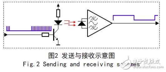
The infrared remote control consists of two parts: transmitting and receiving. The transmitting end uses a single-chip microcomputer to encode and modulate the binary signal to be transmitted into a series of pulse signals, and emit infrared signals through the infrared transmitting tube. The infrared receiving adopts the integrated infrared receiving head with reliable performance to receive the infrared signal. At the same time, it amplifies, detects and shapes the signal, and obtains the encoded signal of TTL level, and then sends it to the single-chip microcomputer, which is decoded by the single-chip microcomputer and performs related operations.
The infrared transmitting and receiving control circuits are all realized by 8051 single-chip microcomputer, the circuit is simple, the output control mode is selectable, and the practicability is strong. Figure 2 is a schematic diagram of transmission and reception:
3. System main hardware design
In this design, the AT89C51 microcontroller is the core. The AT89C51 microcontroller is a low power, low voltage, high performance CMOS 8-bit microcontroller with output pins and command systems compatible with the MCS-51. AT89C51 is a kind of single-chip microcomputer with strong function, high flexibility and reasonable price, which can be easily applied in various control fields.
3.1 Infrared transmitting and receiving device
Here, an infrared light-emitting diode such as SE303·PH303 is used, and the shape is similar to that of the light-emitting diode LED, and infrared light (near-infrared light is about 0.93 um) is emitted. The tube voltage drop is about 1.4V, and the working current is generally less than 20mA. In order to adapt to different working voltages, the circuit has a series of finite current resistors. When infrared rays are emitted to control the corresponding controlled device, the distance controlled is proportional to the transmitted power. In order to increase the infrared control distance, the infrared light-emitting diode operates in a pulse state, because the pulsating light, that is, the effective transmission distance of the modulated light is proportional to the peak current of the pulse, and the peak current can be increased as much as possible to increase the emission distance of the infrared light. . The method of increasing the peak current is to reduce the pulse duty ratio, that is, the width of the compression pulse. Reducing the pulse duty cycle also greatly increases the emission distance of the low power infrared light emitting diode. In order for the infrared light emitting diode to generate modulated light, it is only necessary to add a pulse voltage of a certain frequency to the driving tube.
The design adopts the infrared integrated receiving head HS0038.HS0038 to integrate the receiving, amplifying, detecting and shaping of the remote control signal, and outputs the TTL signal which can be recognized by the single chip microcomputer, which greatly simplifies the complexity of the receiving circuit and the design work of the circuit. ,easy to use.
3.2 Infrared signal encoding processing
3.2.1 Infrared coding
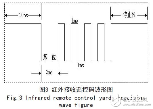
The remote control information code is modulated by the timer T1 of the AT89C51 single-chip microcomputer into a 38.5KHz infrared carrier signal. The different pulse numbers represent different operation code information, at least two pulses (using two), and the number of pulses of other information codes. Increase by one by one. In order to make the reception as reliable as possible, the first bit code width is 3ms, the rest is 1ms, the code spacing is 1ms, and the remote control code data interval is greater than 10ms. Each key on the remote control has a unique key number, and the MCU checks the press. The key value of the key is sent a predetermined number of pulses.
3.2.2 Decoding of infrared receiving signals
The decoding of the received signal is decoded according to the format of the output frame of the infrared receiver, that is, the accumulator A respectively counts the negative transition pulses that meet the condition. When the infrared receiver outputs the pulse frame data, the low level of the first bit code will start the interrupt program and receive the data frame in real time. When receiving a data frame, the code width of the first bit (starting) code is verified according to the format of the transmitted frame. If the pulse width of the first low level code is less than 2ms, it will be treated as an error code. When the high-level pulse of the interval bit is greater than 3ms, the reception ends, and then according to the number of pulses in the accumulator A, it is judged whether the six-digit password input by the keyboard is the same as the set password, thereby controlling whether the relay is unlocked or not. Figure 3 is a waveform diagram of a frame of remote control code output by the infrared receiver.
3.2.3 Communication interface circuit
The communication between the computer and the single-chip microcomputer adopts the serial communication mode. The serial communication is the simplest and most widely used data communication method between the PC serial port and the device at this stage. The serial port is a protocol for common device communication in the computer. The RS-232 interface standard can realize the transmission between data and complete the transmission of temperature data and control commands.
4. System software design
4.1 Remote control launch part programming
This part is mainly divided into main program, button scanning program and remote control code pulse transmitting program. Mainly the setting of the timing of the timer T1, the initialization of the counter, and the like.
4.2 PC software design
This paper also designed the PC software for human-computer interaction, which can expand the application of password locks in a wider field.
This paper uses the LabVIEW graphical programming language to complete the design of the control platform. The system software adopts the modular design idea. The LabVIEW program reads the password lock data through the serial communication circuit and analyzes and processes the data accordingly.
4.2.1 User Management Module
The normal operation of the password lock monitoring system is related to the security of the entire password lock system. Only authorized users can enter the system for operation. Each authorized user has a unique identity, the username, and the user logs in to the system with a password. Users can be divided into three categories according to their permissions: administrators, general users, and test users. Test users can only use some functions of the system; ordinary users can use all the functions of the system; in addition to the rights of ordinary users, administrator users can also manage other users, including adding users, modifying user rights, and deleting users.
4.2.2 Password lock status and display module
The password lock status can be displayed in real time through the LabVIEW front panel on the computer monitor and connected line by point. The block diagram of the data acquisition program is shown in Figure 4.
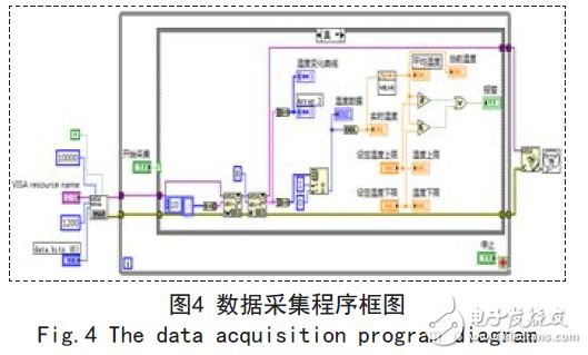
By calling WriteCharacters To File in LabVIEW, the data access module saves the detected password lock status value to the Excel table, which is convenient for the user to recall the historical password lock status value for review.
5. Conclusion
This design uses a single-chip chip to control an infrared remote control system, which overcomes the shortcomings of the traditional lock that must be inserted into the lock to open, and has a remote remote unlock function. And establish the upper computer software to manage the state of the infrared remote control password lock network. The infrared remote control code lock designed in this scheme has the functions of remote unlocking, password modification, password error alarm, etc., and has the characteristics of good confidentiality, safety and reliability, and low cost. After testing, the infrared remote control code lock has strong practicability.
Various products of Epoxy Usb Flash Drive, including Epoxy Usb Flash Drive With Custom Personalized Logo, Epoxy USB Flash Drive, Slide Style Epoxy USB Flash Drive, Plastic Epoxy USB Flash Drive. We also providing product images and basic parameters with each Epoxy USB Flash Drive;

Epoxy USB Flash Drive is An ideal way to store all your pictures, documents, music and videos. Epoxy USB Flash Drive Can act as a wonderful gift for your friends and families and A great way to distinguish your masses of USB flash drives from each other as our cute USB come in a variety of variations for every day use.
- Compatibility: Desktop, Laptop, Macintosh, Tablet, Speakers all with USB1.0 and 2.0.
- Operating System : Windows7/Vista/XP/2000/ME/NT/98,Linux (Sometimes incompatible with Mac OS 9.X/Linux2.4)
- Fine choice for advertisement allow to print LOGOs and advertisement.
- Very Low Power Consumption, durable solid-state storage.
- Small and exquisite design brings much convenience.

We are a professional Chinese manufacturer of Epoxy USB Flash Drive, and look forward to your cooperation!
Epoxy Usb Flash Drive
Epoxy Usb Flash Drive,Paypal Epoxy Type Usb Flash Drive,8Gb Epoxy OEM Usb Flash Drive,Oem Epoxy Custom Usb Flash Drive
Reteck Storage Device Co., Ltd. , https://www.reteck.com