 Since the release of RT-Thread Nano, Xiaobian has received many examples from developers asking for an accompanying tutorial. The official team has now released a guide titled: Starting from bare metal, creating an RT-Thread Nano system project, but for most developers, it still feels insufficient. Fortunately, RT-Thread developer Yan Thirteen created a hands-on tutorial that's easy to follow. Even someone with no technical background can understand it. Join RT-Thread and get your free T-shirt today.
 Call for papers | You can't write, but here's some free stuff!


What is RT-Thread Nano? As you might know, Keil5 now uses pack files to manage chips and related components. RT-Thread Nano is also distributed through the Keil pack method. It provides minimal Flash and RAM usage while maintaining essential features. By default, Flash usage is as low as 2.5K and RAM as low as 1K.
Currently, the pack includes three main functions: kernel, shell (msh), and device drivers. These can be loaded on demand based on your needs. The main chip used in this example is GD32F150C8T6, which has 64K Flash and 8K RAM.
First, Download and Install RT-Thread Nano Pack 
1. On the main interface of Keil5, click the “Pack Install†button to open the Pack Installer.
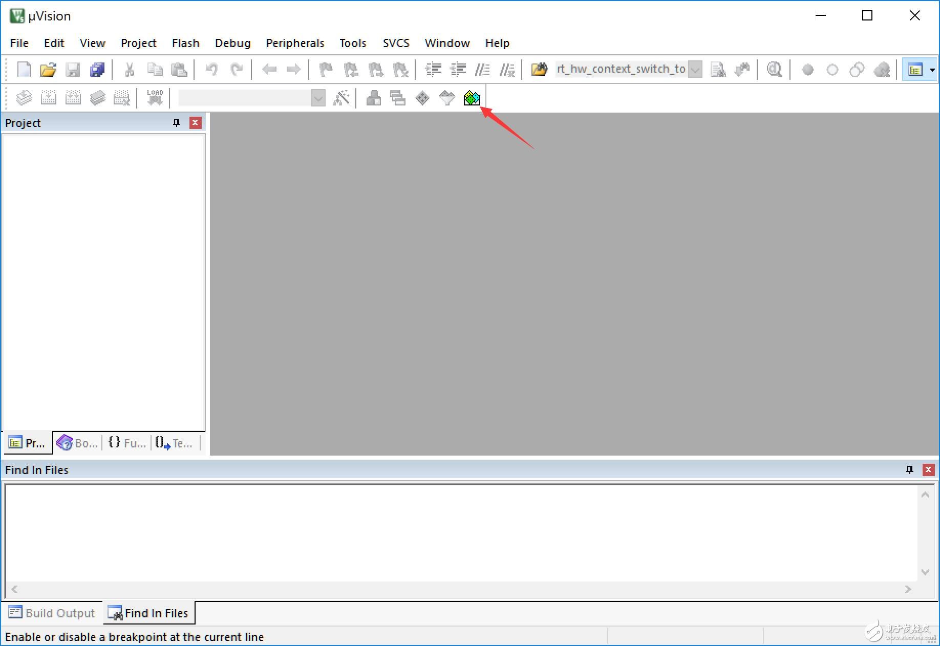
Figure 1: Keil5 main interface
2. In the Pack Installer, look for the RT-Thread Pack on the right side. If it’s not installed, click "Install." If it’s already installed, you may see an "Update" prompt.
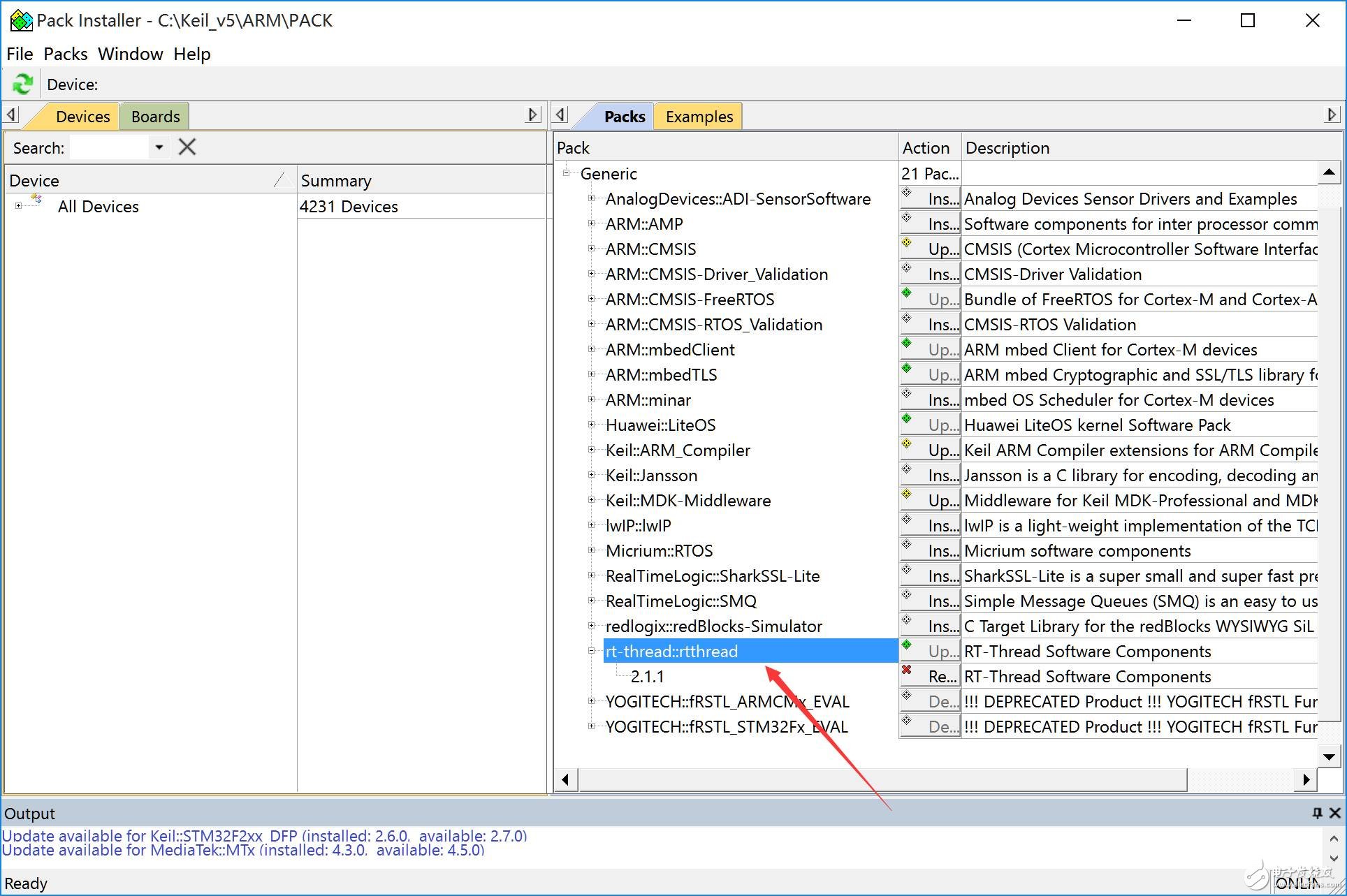
Figure 2: RT-Thread Pack download
3. If you don’t see "RT-Thread" in the Packs section, click "Check for Updates" under the "Packs" menu. After updating, the RT-Thread Pack should appear.
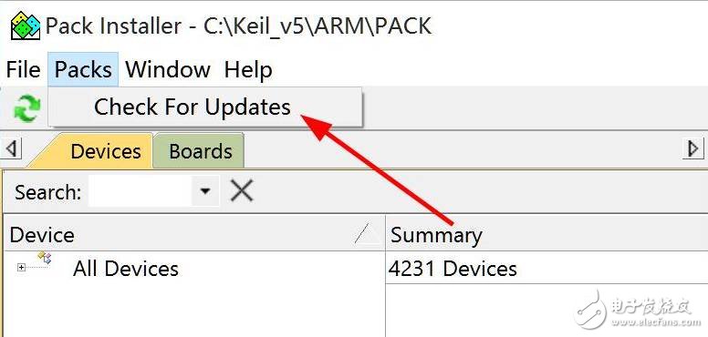
Figure 3: Pack Update
4. Once the package is downloaded, Keil will automatically pop up the installation window. Follow the steps to complete the installation.
Second, Create a Bare-Metal Minimum Project 
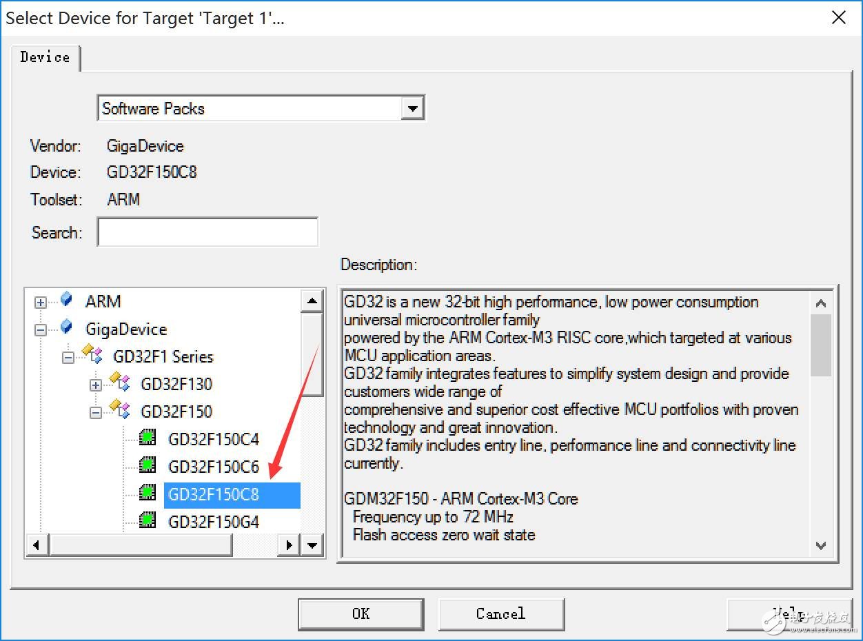
1. This project uses the GD32F150C8T6 microcontroller, which has 64K Flash and 8K RAM. First, download and install the GigaDevice.GD32F1x0_DFP.pack from the official website in Keil5.
2. Build the project according to the standard bare-metal process in Keil. The minimum project only contains necessary library files, and the main function does no extra processing.
Figure 4: GD32F150C8T6 minimum project
3. After compilation, the default Flash size is 1112 bytes, and RAM is 2144 bytes.
4. Modify the startup file startup_gd32f1x0.s to set the heap and stack sizes. The default heap is 0x400, and the stack is 0x400. For RT-Thread, we’ll set the heap to 0 and adjust the stack size based on your application needs.
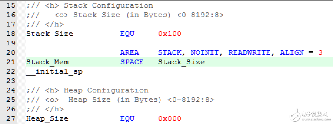
Figure 5: Startup file stack and heap modification
After the changes, RAM usage drops to 352 bytes.
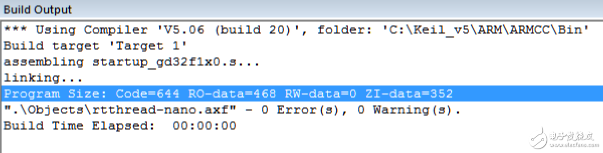
Figure 6: Flash and RAM after heap and stack adjustment
Third, Load Kernel and Application 
1. Load RT-Thread Kernel: Click the “Manage Run-Time Environment†button on the main interface to enter the configuration page.
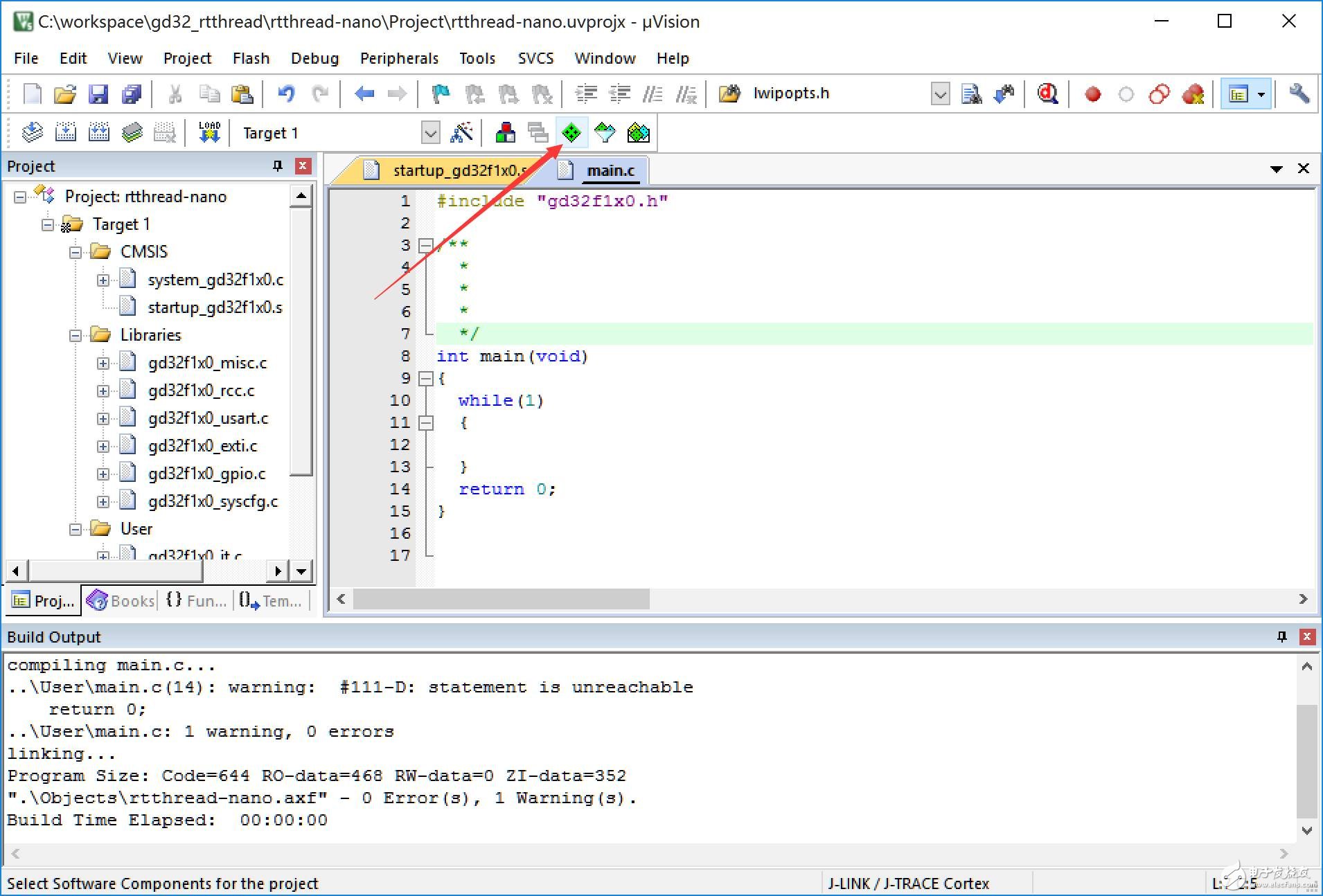
Figure 7: Manage Run-Time Environment
Select “RT-Thread†under the “RTOS†column and choose “kernel†from the list. The current version is 2.1.2.
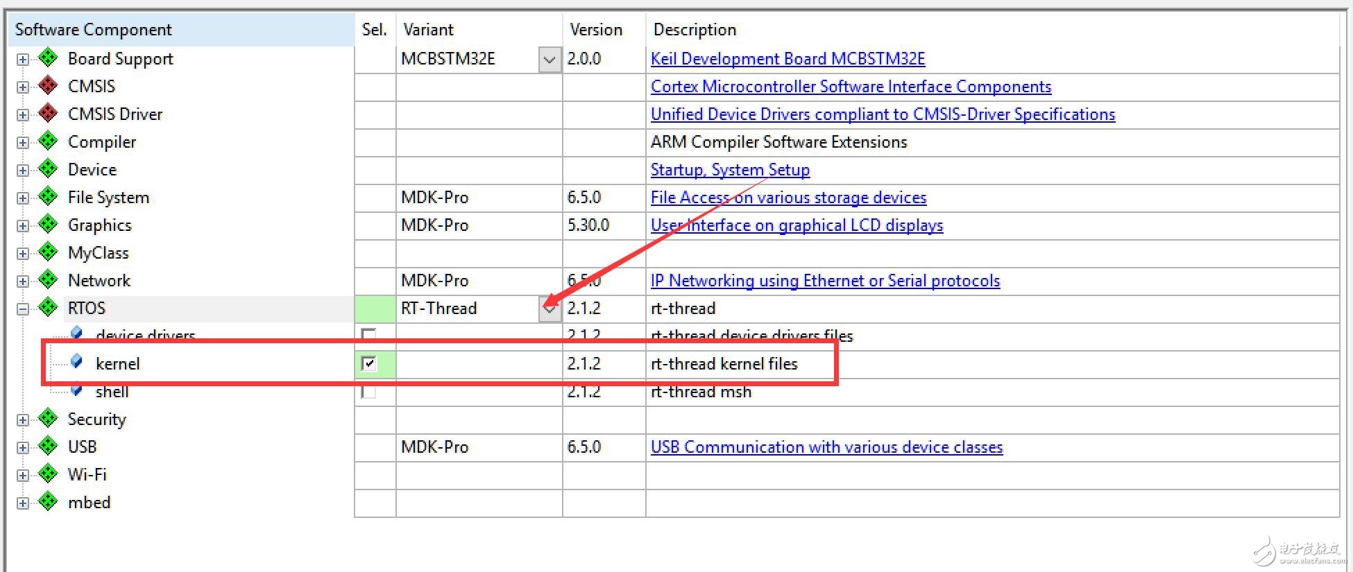
Figure 8: RT-Thread kernel selection
2. After confirming, the RT-Thread kernel files and M3 porting code will be added to your project based on the selected chip.
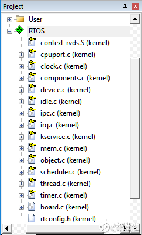
Figure 9: RT-Thread kernel files
Among them are:
Clock.c
Components.c
Device.c
Idle.c
Ipc.c
Irq.c
Kservice.c
Mem.c
Object.c
Scheduler.c
Thread.c
Timer.c
Cortex-M3 porting code:
Cpuport.c
Context_rvds.s
Application code and config files:
Board.c
Rtconfig.h
3. After compiling again, you may see repeated function definitions. Make the following modifications:
a) In gd32f10x_it.c, remove these functions:
Void HardFault_Handler(void)
Void PendSV_Handler(void)
Void SysTick_Handler(void)
b) Modify board.c as instructed.
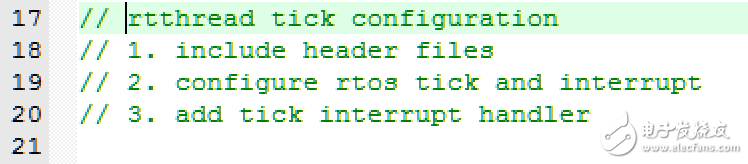
Figure 10: Board.c modification instructions
Modify line 24: #include "gd32f1x0.h"
Modify line 48: Enable SysTick_Config in rt_hw_board_init()
Modify line 66: void SysTick_Handler(void)
4. In main.c, add:
#include
Add rt_thread_delay(100) inside the while loop.
5. After recompiling, download to the chip and run. You'll see the main function being interrupted every second, indicating the RT-Thread scheduler is working.
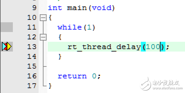
Figure 11: RT-Thread running normally
You can check the .map file to see the resource usage. Without optimization, you'll see each file's memory usage in the RT-Thread kernel.
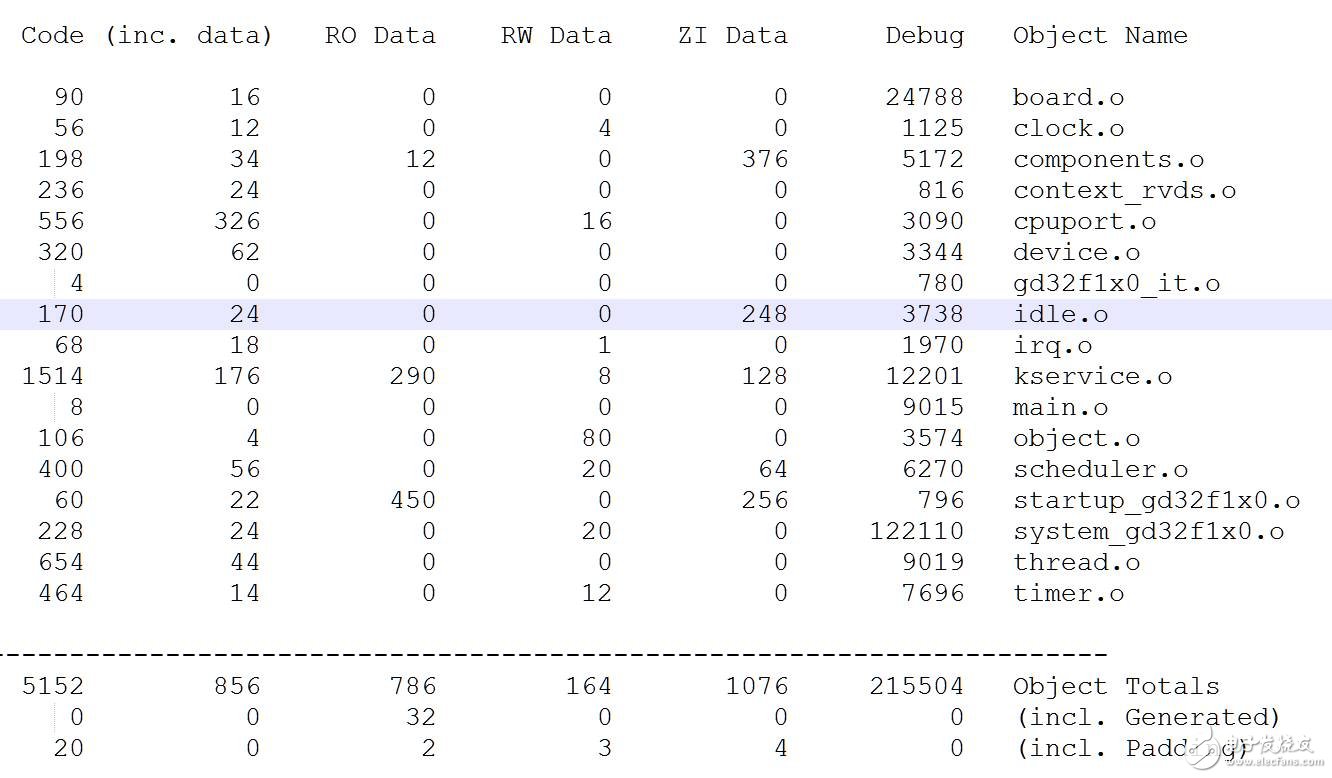
Figure 12: Resource usage table
6. To add features like tasks, timers, and semaphores, modify the main function. The default rtconfig.h only supports static creation. To use dynamic features, enable RT_USING_HEAP. Details are in the fifth part of this guide.
Fourth, Analyze RT-Thread Startup Process 
Although this Keil project uses RT-Thread, the development process is similar to traditional OS development. Both start with main(), initialize hardware, and apply RT-Thread functions directly. But how does the scheduler run without explicit initialization? Let’s find out.
01
RT-Thread EntryIn the components.c file, line 140, there's a macro definition #ifdef RT_USING_USER_MAIN. This is defined in rtconfig.h. Also, on line 146, we see #if defined (__CC_ARM), which refers to the ARM compiler in Keil.
Here, two functions are defined: $$Sub$$main() and $$Super$$main(). The $$Sub$$main() function inserts code before main() to extend its functionality without changing the source. The linker replaces main() by calling $SubSub$$Main(), then returns to main() via $$Super$$main.
#if defined (__CC_ARM)
Extern int $Super$$main(void);
/* re-define main function */
Int $Sub$$main(void)
{
Rt_hw_interrupt_disable();
Rtthread_startup();
Return 0;
}
The functions rt_hw_interrupt_disable() and rtthread_startup() are called in $Sub$$main(). These are standard RT-Thread boot functions.
rtthread_startup() performs:
- System timer setup
- Timer initialization/startup
- Idle task creation
- Application thread initialization
- Scheduler start
02
Application Thread Entry rt_application_init()Void rt_application_init(void)
{
Rt_thread_t tid;
#ifdef RT_USING_HEAP
Tid = rt_thread_create("main",main_thread_entry, RT_NULL,
RT_MAIN_THREAD_STACK_SIZE, RT_THREAD_PRIORITY_MAX / 3, 20);
RT_ASSERT(tid != RT_NULL);
#else
Rt_err_t result;
Tid = &main_thread;
Result = rt_thread_init(tid,"main", main_thread_entry, RT_NULL, main_stack, sizeof(main_stack),RT_THREAD_PRIORITY_MAX / 3, 20);
RT_ASSERT(result == RT_EOK);
#endif
Rt_thread_startup(tid);
}
The application thread creates a task called main_thread_entry and starts it. Let’s take a closer look at main_thread_entry.
/* the system main thread */
Void main_thread_entry(void*parameter)
{
Extern int main(void);
Extern int $Super$$main(void);
/* RT-Thread components initialization */
Rt_components_init();
/* invoke system main function */
#if defined (__CC_ARM)
$Super$$main(); /* for ARMCC. */
#elifdefined(__ICCARM__) ||defined(__GNUC__)
Main();
#endif
}
The main_thread_entry task calls rt_components_init() and enters the real application main function.
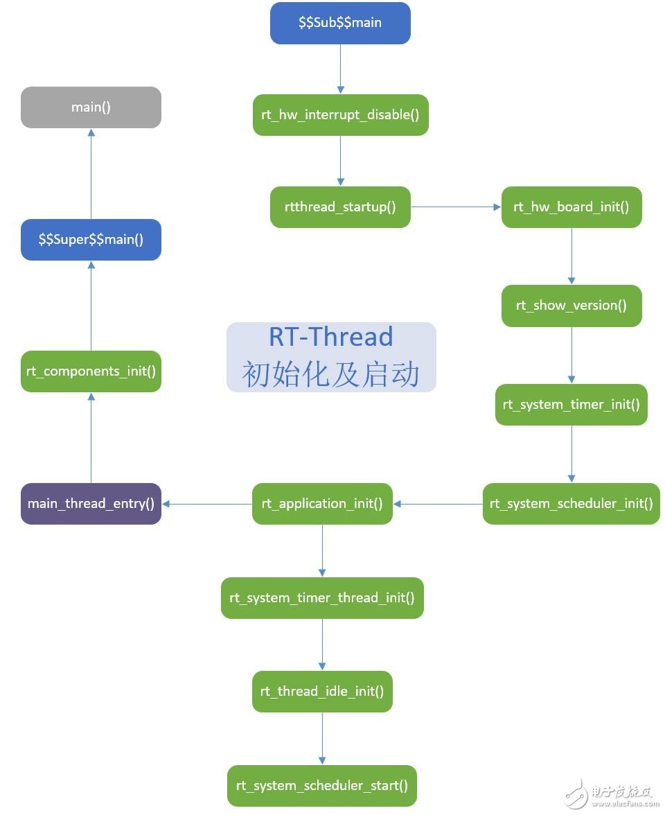
Figure 13: RT-Thread initialization and startup process
From the analysis, the RT_USING_USER_MAIN option in rtconfig.h allows the compiler to insert $$Sub$$main() before main(), initializing RT-Thread and starting the scheduler. Then, the main_thread_entry task runs, returning to main() via $$Super$$main(). So, the main() function is actually a task in RT-Thread. Its priority is RT_THREAD_PRIORITY_MAX / 3, and the stack size is RT_MAIN_THREAD_STACK_SIZE.
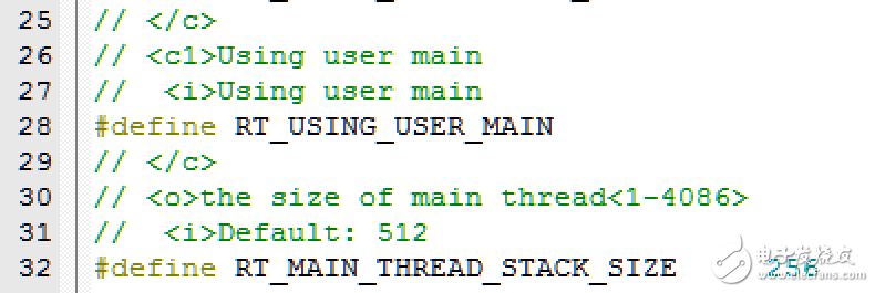
Figure 14: RT_USING_USER_MAIN option
Fifth, RT-Thread Configuration (rtconfig.h) 
RT-Thread is highly configurable via the rtconfig.h file. Nano achieves a 2.5K Flash and 1K RAM footprint, but since RT_USING_HEAP is disabled, it only supports static tasks and semaphores. Here’s how to configure common options in rtconfig.h.
0 1
RT_USING_HEAP: Enable HeapBased on the chip model in board.c, line 37, adjust SRAM_SIZE. The default is 8, and for GD32F150C8T6, it’s also 8K.

Figure 15: SRAM_SIZE configuration
After enabling RT_USING_HEAP, rt_system_heap_init() is called in rt_hw_board_init() of board.c
#if defined(RT_USING_USER_MAIN)&& defined(RT_USING_HEAP)
Rt_system_heap_init((void*)HEAP_BEGIN,(void*)SRAM_END);
#endif
Where:
SRAM_END: defined as 0x20000000 + SRAM_SIZE * 1024
HEAP_BEGIN:
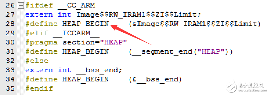
Figure 16: HEAP_BEGIN definition
Image$$RW_IRAM1$$ZI$$Limit is a linker symbol indicating the end of the ZI segment.
Once configured, you can dynamically create tasks, semaphores, etc.
0 2
RT_USING_TIMER_SOFT: Enable Software Timer
The default Nano configuration doesn’t include software timers. Enabling this allows multiple software timers with Systick accuracy.
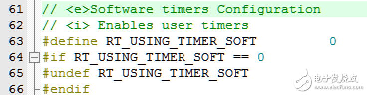
Figure 17: Software Timer Enabled

- End -
1. PC-SVC series Servo motor control Voltage Stabilizer has the low energy consumption,the over voltage protection,the low voltage protection,the over-current protection,the over-loading protection,the over-temperature protection and so on.It boasts for many kinds of protections,the collection energy conservation and the environmental protection ect.This is a brand-new concept product which possess many new technologies!This series products simultaneously ha applied for many technical monopolies
We already applied many kinds of this products patent, and the technical patent NO: 200720036394.1 and Appearance paten NO: 200730025909.3
2. Use for equipment:
Computer
Test equipment
Light system
Safe alarm system
Ray equipment
Medical equipment
Copy machine
Stereo equipment
Numerical control machine tools
Industrial automation equipment
Color and drying equipment
Test equipment
Hi-Fi equipment
Servo Moto Voltage Stabilizer,Servomax Stabilizer,Servo Controlled Voltage Stabilizer,Main Line Stabilizer
zhejiang ttn electric co.,ltd , https://www.ttnpower.com