UC3842A UC3843A Information
The UC3842A and UC3843A are high-performance fixed-frequency current-mode controllers designed for both offline and DC-to-DC converter applications. These controllers provide designers with a cost-effective solution requiring minimal external components. Key features include a trimmable oscillator, precise duty cycle control, temperature-compensated reference, and a high-gain error amplifier. The current-sampling comparator and high-current totem-pole output make these devices ideal for driving power MOSFETs. Protection features include input and reference undervoltage lockout with hysteresis, cycle-by-cycle current limiting, programmable output dead time, and single-pulse measurement latching. These ICs are available in 8-pin dual-in-line plastic packages and 14-pin plastic surface-mount packages (SO-14). The SO-14 package includes separate power and ground pins for the totem-pole output stage.
The UC3842A operates with low-voltage lockout thresholds of 16V (on) and 10V (off), making it suitable for offline converters. The UC3843A is designed for low-voltage applications with lower lockout thresholds of 8.5V (on) and 7.6V (off).
Key Features:
- Fine-tuned oscillator discharge current for precise duty cycle control.
- Current mode operation up to 500 kHz.
- Automatic feedforward compensation and latch pulse-width modulation.
- Internally trimmed reference voltage with undervoltage lockout.
- High-current totem-pole output.
- Undervoltage lockout with hysteresis.
- Low startup and operating current.
- Direct interface with ON Semiconductor’s SENSEFET products.
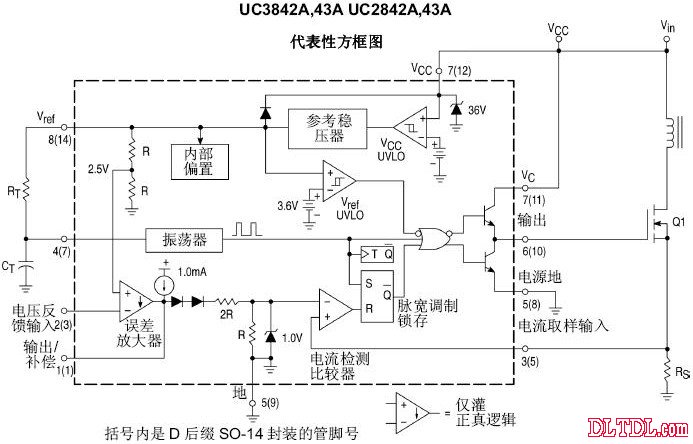
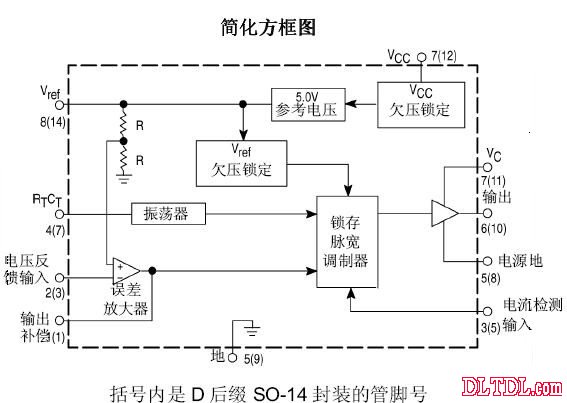
Figure 1
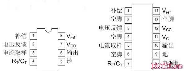
Figure 2 - Pin Diagram
Pin Function - Pin Function Description
| Pin 8 | 14 Pin | Compensates | This pin is the error amplifier output and can be used for loop compensation. |
| Pin 3 | Voltage Feedback | This pin is the inverting input of the error amplifier and is typically connected to the switching power supply output through a resistor divider. | |
| Pin 4 | Current Sampling | A voltage proportional to the inductor current is connected to this input, and the pulse-width modulator uses this information to abort the conduction of the output switch. | |
| Pin 5 | - Ground | This pin is the common ground for the control circuit and power supply (only for the 8-pin package). | |
| Pin 6 | 10 Output | Directly drives the gate of the power MOSFET. The peak current of up to 1.0A is pulled and filled through this pin. | |
| Pin 7 | 12 VCC | Positive supply for the control IC. | |
| Pin 8 | Power Ground | This pin is a separate power return to the power supply return (14-pin package only) to reduce the effects of switching transient noise in the control circuit. | |
| Pin 11 | Vref | Reference output, which supplies the charging current to the capacitor CT through the resistor RT. | |
| Pin 13 | Empty Feet | Not connected (only 14-pin package). |
The following figure shows the UC3842 application circuit diagram for a display.
Image 3
UC3842 Good and Bad Judgment and Identification Method
In domestic electronic equipment, the most commonly used integrated circuit model for the power supply PWM control circuit is the UC3842 (or KA3842). It is frequently encountered, so here's a brief introduction to the judgment method of the UC3842:
After replacing the damaged components, do not install the switch (MOSFET), power up to measure the voltage of pin 7 of the UC3842. If the voltage fluctuates between 10-17V, the other pins will also show fluctuating voltages, indicating that the circuit has started and the UC3842 is basically normal. If the voltage of pin 7 is low, and the other pins have no voltage or do not fluctuate, then the UC3842 is damaged.
Add a DC voltage of about +17V between pins 7 and 5 of the UC3842. If pin 8 has a voltage of +5V and pins 1, 2, 4, and 6 also have different voltages, the UC3842 is basically normal, the working current is small, and it is less likely to damage itself. The most common cause of damage is when the power switch (MOSFET) shorts out, causing high voltage to be applied to pin 6, which burns out the IC. In some models, the G-grounded protection diode is omitted. When the power switch (MOSFET) is damaged, the current-limiting resistors of the UC3842 and G poles must be replaced. At this point, simply replace them.
It should be noted that the source (S pole) of the power switch is usually connected to a small resistance, high-power resistor as an overcurrent protection detection resistor. The resistance of this resistor is generally between 0.2 and 0.6 ohms. Above this value, there may be a phenomenon where the load cannot be loaded (i.e., the secondary pole voltage is low).
Since the working voltage and output power of UC3842 (KA3842) are far from those of UC3843 (KA3843), the 3842 series and 3843 series also differ significantly in starting voltage and cutoff voltage. The former has a starting voltage of 16V and turns off at 10V; the latter has a starting voltage of 8.5V and turns off at 7.6V. These two series of ICs cannot be directly replaced. If it is necessary to replace the former with the latter, the circuit must be modified. Therefore, this must be kept in mind during maintenance work.
Frame For Iphone,Metal Frame For Iphone,Series Frame With Glue,Frame For Iphone Xs
Shenzhen Xiangying touch photoelectric co., ltd. , https://www.starstp.com