0 Preface
In the context of increasing environmental pollution and energy scarcity, LED lighting equipment has been widely used due to its high luminous efficiency and long service life. As the theme of future lighting, LED lighting systems are moving towards intelligent direction. Personalization, comfort and secondary energy savings in LED lighting are achieved through a combination of sensing, communication and control technologies. The basic functions of the intelligent lighting control system include: brightness control of the LED device, collection of physical parameters such as current, voltage and power factor of the LED driver, and detection of the working state of the device. The control methods of intelligent lighting control systems can be divided into wired and wireless. Common wired control methods include DALI, PLC and RS485. Wireless control mainly uses 433MHz and Zigbee network to transmit signals.
The ANT Wireless Ad Hoc Network Protocol is a 2.4GHz short-range wireless network standard introduced by companies such as Dynastream and Nordic. It has lower power consumption, lower system cost and shorter than wireless communication technologies such as Bluetooth and Zigbee. The advantages of development and application cycle are short-range wireless communication technologies with strong competitiveness.
1 system architecture
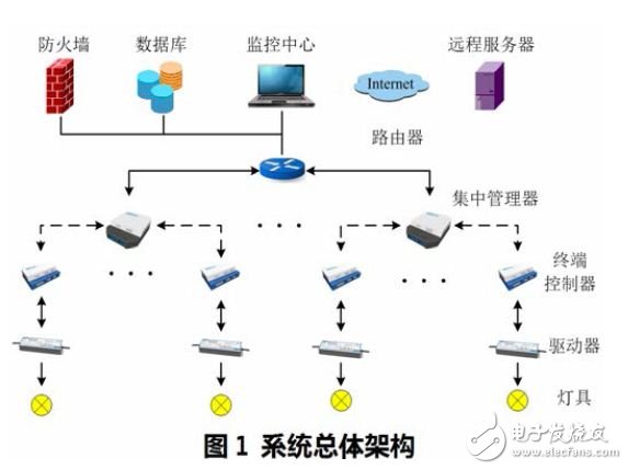
As shown in Figure 1, the control system consists of server software, a centralized manager, and a terminal controller. The top-level server is located in the remote control center and exchanges data with the centralized manager via Ethernet, GPRS or 3G. The user can use the management software installed on the server to view the real-time electrical parameters and working status of the lighting device, and configure the lighting control strategy. The centralized manager is used to implement two-way communication relay between the server and the terminal controller. On the one hand, the server command is received and sent to the controller for lighting control, and the controller state and electrical parameters are queried and uploaded to the server. The ANT wireless network communicates between the centralized manager and the terminal controller. The terminal controller at the bottom layer is connected to the LED driver and is responsible for monitoring the working state of the LED lighting device and collecting relevant electrical parameters, and adjusting the brightness level of the LED light source according to the command.
2 hardware design
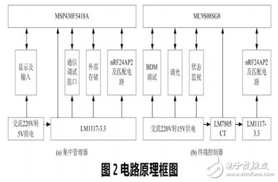
The circuit block diagram of the centralized manager and terminal controller is shown in Figure 2. The centralized manager is mainly responsible for communication relay. Its processor selects TI's 16-bit ultra-low-power single-chip MSP430F5418A. Its peripheral functions are rich, and it integrates UART, SPI, I2C and other interfaces to facilitate interconnection with external systems. Expansion requirements for communication modules. The terminal controller changes the brightness of the LED by controlling the dimming voltage of the input driver or the duty cycle of the PWM. By collecting the feedback voltage of the LED driver to determine whether the LED driver is operating normally, the processor uses the 8-bit microcontroller of Freescale. The MC9S08SG8, which features four PWM outputs and eight ADCs, is ideal for light control systems.
The ANT network chip uses Nordic's second-generation single-chip ANT solution product, nRF24AP2, which provides a synchronous/asynchronous serial interface. In this design, the microcontroller and the nRF24AP2 chip communicate via an asynchronous serial port. The ANT protocol stack is pre-packaged in the nRF24AP2, so the microcontroller can simply send command data frames to the nRF24AP2 in the specified format to implement networking and communication. The ANT serial data frame starts with the synchronization code, ends with the check code, and transmits the byte with the low-order preamble. The data frames are in turn composed of the following:
(1) Synchronization code (1 byte): the data sent by the processor to the ANT chip is 0xA5 as the synchronization code, and the data sent by the ANT chip to the processor starts at 0xA4;
(2) Frame length (1 byte): User data length, up to 9 bytes;
(3) Frame type (1 byte): data frame type, valid values ​​are 1~255;
(4) Data (N bytes): User-defined communication data;
(5) Check code (1 byte): equal to the XOR value of all previous bytes.
3 software design
The ANT network provides a variety of network topologies such as point-to-point, star, tree or even mesh to meet the needs of different lighting environments. This design uses a chain network configuration for streetlight applications. In a chain network, the commands sent by the centralized manager and the data replied by the terminal controller need to be transmitted to the target address by multi-hop forwarding.
ANT is based on channels for network management and communication. A channel is a communication path for data exchange between ANT devices. Each channel consists of 1 host and 1 to more slaves.
ANT devices with matching channel parameters can communicate with each other. As the active sender of the command, the manager is the source device of the chain network, which is configured as the host of the channel. The terminal controller (except at the end of the link) needs to relay the communication, so it works on 2 channels at the same time, acts as a slave on the channel receiving the command, and acts as the master on the channel that sends the command.
Channel parameters include channel type, channel ID, operating frequency, channel period, and network type. The channel configuration is performed in the following sequence:
(1) Configure the network type: use the public network and the public network key;
(2) Allocating channels: the designated host adopts a shared bidirectional transmitting channel, and the slave adopts a shared bidirectional receiving channel;
(3) Configure channel ID: The transmission type, device type and device number of the host are 3, 4 and 4 respectively. The settings of the slaves working in a channel are the same as those of the channel in which they are located;
(4) Configure the channel period, wireless communication frequency and transmission power: set to 2 seconds, 2466MHz and 0dBm respectively;
(5) Open the channel.
The functions of the Central Manager include communication relay and timing query controller status. After power-on, the centralized manager first initializes the microcontroller: configure the clock, the baud rate of the asynchronous serial port, etc., and enable the serial port and timer interrupt. After the initialization is completed, the centralized manager operates the nRF24AP2 to complete operations such as power-on reset and channel configuration, and then enters a low-power state. Receiving the server command and the controller response will trigger the microcontroller to enter a different serial port interrupt handler. Upon receiving the server command, the centralized manager first parses the command frame and obtains the target controller address and sends a command to it. When the object of the issued command is a single controller, the centralized manager waits for the response of the controller after sending the command. If the data replied by the target controller is received within the specified time, the centralized manager will save the data and update its wireless communication status information; otherwise, the centralized manager will resend the command frame until receiving the response or retransmission times of the controller. to reach maximum. If the object to which the command is issued is a group of controllers, the centralized manager waits for a period of time after sending the command, and sends a query command to confirm whether the target controller has performed the corresponding operation according to the command. In addition, the centralized manager also periodically queries the operating status and electrical parameters of all lighting devices.
The routing terminal controller enters a low power state after completing the initialization of the microcontroller and configuring the nRF24AP2. Since they work on both channels simultaneously, they receive data from 2 channels. There are many types of commands sent by the channel host, which may be dimming or query status. The target address of the command may also be single or multiple. The routing terminal controller does different processing for different types of data. In the case of receiving a unicast command, the controller first determines the target address of the command, and if it is sent to itself, replies to the data, and adjusts the duty cycle of the PWM according to the dimming level in the command, and finally exits the interrupt back to low. The power state; if it is not sent to itself, it will continue to forward commands to the slave on another channel after the response. Similarly, if receiving the data sent by the slave, the routing terminal controller will first check the target address. If it is sent to the manager, it will be sent through the uplink channel. If it is a response to the command issued by itself, then it will return. Exit to interrupt. On the other hand, if the command received by the routing terminal controller is of a multicast type, it first determines whether it is included in the target address set, and if not, it only answers the host and forwards the data. Otherwise, the routing terminal controller waits for a period of time, and when receiving the reply data of the end controller to the centralized manager query command, the local data is encapsulated and sent to the channel host. The advantage of this is that multiple controllers can use the same communication packet to reply data to the centralized manager without having to reply one by one to avoid wireless communication conflicts and congestion.
In addition, the terminal controller also periodically checks whether the operating voltage of the driver is normal and collects relevant electrical parameters.
The function of the terminal controller is relatively simple. In addition to periodically checking whether the working voltage of the driver is normal and collecting relevant electrical parameters, it is only necessary to respond after receiving the issued command and perform corresponding operations according to the command.
4 Summary
Intelligent lighting is the future direction of LED lighting control systems. This paper is based on ANT network communication technology to design the wireless LED lighting control system and its hardware and software. The system does not need wiring, is easy to install, reliable in operation, can improve the intelligent level of the lamp control system, and effectively guarantee the normal operation of the lighting equipment.
Iseeled's Signal Splitter gives you the ability to plug in up to 8 dmx-out from one dmx-in. Led splitter is specially designed for connection of dmx receivers .Our dmx splitter can surmount the restriction that signle RS485 can only connect 32 sets of equipment. DMX splitter is an optical for DMX512 lighting. It's purpose is to allow the user more flexibility in connecting their DMX controller devices. Instead of having to make them all fit within a single daisy chain, each of the eight outputs from the Signal Splitter can be start of its own chain.
Photo show of Signal Splitter:

Signal Splitter
Signal Splitter,Led Signal Splitter,Dmx Signal Splitter,Signal Fiber Splitter
Shenzhen Iseeled Technology Co., Ltd. , https://www.iseeledlight.com