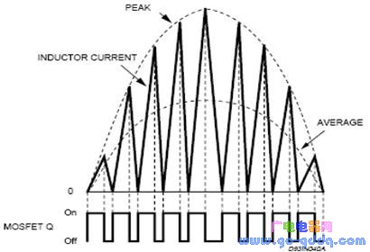
The L6562 operates in peak current mode, where the output voltage feedback is multiplied by the sensed input voltage to determine the peak inductor current. This results in a high-frequency triangular waveform that is enveloped by a 100 Hz sinusoidal signal. After filtering, the input current becomes a sinusoidal waveform that is in phase with the input voltage. In theory, this leads to a power factor (PF) of 1. The inductor current waveform in a boost configuration is illustrated below.
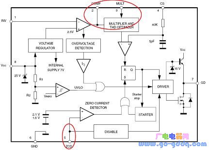
To reduce system cost, the L6562 is often used in a flyback topology to implement single-stage PFC. The principle block diagram is shown above. Its operation is similar to that of a boost converter. The secondary side output voltage feedback is multiplied by the detected primary input voltage to set the peak current on the primary side. The resulting primary input current forms a high-frequency triangular waveform that is modulated by a 100 Hz sine wave. After filtering, the input current becomes a sinusoidal waveform in phase with the input voltage. The primary and secondary currents are depicted in the figure below.
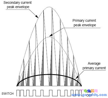
From the figure, two key observations can be made:
a. The transformer operates in Discontinuous Conduction Mode (DCM);
b. The primary current is discontinuous, meaning it only flows during the Ton period of each switching cycle. Therefore, theoretically, a power factor of 1 cannot be achieved in a flyback topology due to this intermittent behavior.
This limitation highlights the importance of selecting the appropriate topology based on the desired performance characteristics and application requirements. While the flyback topology offers cost-effective solutions, it may not be ideal for applications demanding high power factor and continuous current flow.
Solar Energy Storage,Battery System,Battery Structure,Lifepo4 Battery Cells
Guangdong Yuqiu Intelligent Technology Co.,Ltd , https://www.cntcetltd.com