0 Preface
With the rapid development of microelectronics technology, single-chip microcomputers have been widely used in automotive, communications, office automation, industrial control, advanced toys, household appliances and so on. If you use Proteus as a microcontroller system simulation tool, you don't need to make a board, you can use Proteus for system virtual implementation, which not only can complete the required function design verification, but also reduce the hardware cost, thus shortening the entire design cycle. Fundamentally improved the development efficiency of electronic products.
Speed ​​measurement is a problem often encountered in industrial and agricultural production. Based on the various advantages of single-chip microcomputer, it is very important to apply single-chip microcomputer to the speed measurement system. For speed measurement technology, the first problem to be solved is the sampling problem. When using the analog technology to make the speed measuring equipment, the method of measuring the speed generator is commonly used, that is, the rotating shaft of the speed measuring generator is connected with the shaft to be tested, and the voltage level of the speed measuring generator reflects the level of the speed; while using the single chip microcomputer for measuring the speed, the simple speed can be used simply. Pulse counting method.
As long as the rotation axis rotates once, one or a fixed number of pulses are generated, and the pulse is sent to the single-chip microcomputer for counting, and finally the number of pulses per unit time is calculated, and the information about the rotation speed can be obtained. In this paper, based on the capture function of PIC16F877 microcontroller, the pulse counting is completed, and the related physical relationship is converted by software programming. Finally, the gear line speed is obtained and displayed on the digital tube.
1 Speedometer principle
1.1 CCP1 capture function
There are two CCP modules in the PIC16F877 microcontroller, which are basically the same, labeled CCP1 and CCP2. Each CCP module can be arbitrarily configured to capture, compare, and pulse width modulation (PWM). one.
The capture mode of CCP1 has the following three functions: one is to capture the transition of the RC2/CPP1 pin and save the contents of the TMR1 count register at the time; the other is to have a prescaler that can implement every 1 pulse, every 4 pulses. One pulse or 16 pulses are captured once; the third is that the capture time can generate an interrupt.
1.2 CCP tachometer principle
In the capture mode, the microcontroller can capture the time value of the pin change time, which is the exact time value of the rising edge or falling edge of the pin input pulse.
When the CCP1 module of the PIC16F877 is operating in Capture mode, the TMR1 timer's count value is immediately copied to CCPR1H and CCPR1L when a specific edge transition occurs, and an interrupt is generated by reading the 16-bit counter in the interrupt service routine. value. When the measurement of the adjacent two rising edge time intervals is implemented using the capture function of the CCP1 module, this time interval is the period of the input signal g-Period. Since the main frequency is 4 MHz, that is, each instruction cycle is 1 μs, it will be pre- The division ratio is set to 1:1, and the measured period results are in microseconds. So the final measured speed value speed is given by the following formula:
Speed=(1M*60s*0.01m*pi)/g_Period
Where pi is the pi value; 0.01m is the diameter of the gear of the object to be measured, and is measured by a physical method.
Speed=(1M*60s*0.01m*pi)/g_Period
Where pi is the pi value; 0.01m is the diameter of the gear of the object to be measured, and is measured by a physical method.
2 function realization
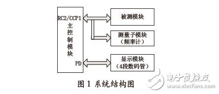
2.1 System Design Block Diagram
The realization of the tachometer function can be composed of several parts, such as the main control module based on PIC16F877, display module, gear and photoelectric sensor.
The RC2/CCP1 pins of the microcontroller are connected to the module under test and the measurement submodule respectively. When the Proteus software is simulated, the signal generator SG1 and the frequency meter are connected as hardware devices. SG1 is used to simulate the signal generated by the module under test. F1 is operated by frequency meter to display the current signal frequency. It is used to compare the reference value with the display module data, that is, the speedometer result value to verify the speedometer's speed measurement result. Correct or not. The connection relationship between the modules is shown in Figure 1.
2.2 Scheme design and implementation
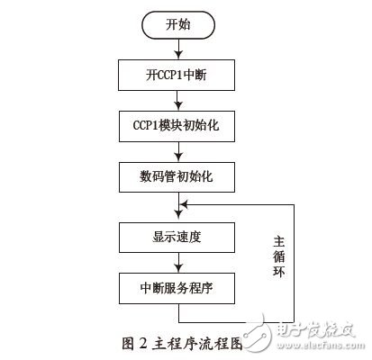
The design of this simple speedometer is based on the CCP module function of the PIC16F877. Here we first configure the CCP1 of the PIC16F877 to capture mode with the prescaler set to 1:1 and trigger on each rising edge.
When the CPP1 interrupt flag bit is captured after the jump, the interrupt mode is used for processing, that is, the value or state change of the relevant register is processed in the interrupt service subroutine, and the relevant physical quantity is calculated and stored. The above settings are all completed by software programming.
SHENZHEN YINZHIGUAN DIGITAL TECHNOLOGY CO.,LTD , http://www.yzgmusiccrown.com