Design and Implementation of High Definition Digital TV Transmission System
Transmitting high-definition digital TV within a limited bandwidth places higher requirements on video, audio compression coding, and channel coding, and in the case of terrestrial transmission? Various attenuation and interference in the wireless environment are also inevitable, while considering To meet the reception requirements in the mobile environment, the latest technology of wireless communication must be introduced in the new generation of terrestrial digital TV transmission systems. The combination of digital TV broadcasting and modern digital communication technology has enabled traditional TV media to regenerate on the basis of communication networks.
Tsinghua University has completely developed the terrestrial digital multimedia TV broadcast transmission protocol DMB-T? On the basis of comprehensively absorbing the advantages of the existing high-definition digital TV standards abroad and applied for a service invention patent. At the 2nd China International High-tech Achievement Fair held in Shenzhen, Tsinghua University fully demonstrated this technology, which was affirmed by many experts.
Cadence's system-level design and simulation software SPW Signal Processing Worksystem was used in the DMB-T system design. In large-scale system design, only the implementation of algorithms and system-level optimization can greatly improve the performance of the system, because it has more optimization space than the underlying optimization.
Take Cadence's software tools as an example? The corresponding system-level design flow is shown in Figure 1. 
The traditional electronic design process usually starts from the hardware description language VHDL or Verilog? The hardware-related optimization is directly performed and the optimization of the real high-level algorithm is very limited. This design idea is more suitable when the system scale is small and the corresponding algorithm is relatively mature. Now the scale of electronic design is getting larger and the complexity is getting higher and higher. The previous process will no longer meet the needs.
The system-level design method refers to the use of special system-level design tools such as SPW for algorithm development first. The difference from the traditional design method is that the system-level design tool can free the user from the cumbersome hardware implementation and concentrate on the corresponding The algorithm is developed, and the feasibility of the system algorithm is verified through simulation to obtain the performance index. After the algorithm is determined, the designer then converts the results of the system-level design into the hardware description language VHDL or Verilog through the hardware design system (Hardware Design System) and the hardware-software co-simulation interface Co-Sim, and then uses FPGA or ASIC.
1 Ideal system emulation Digital TV transmission system involves many subsystems of modulation, coding, sending and receiving, decoding, demodulation, but the modeling of the channel is of great significance to the performance of the system. The core technology used in DMB-T is OFDM orthogonal frequency division multiplexing, which is a great improvement over the European DVB-T in channel estimation and synchronization algorithms. In the design methodology, we can first consider the establishment of an ideal transmission channel where channel noise and interference do not exist, focusing on the design of modulation, demodulation, coding and decoding systems, and first establish an ideal system model.
The description of the modulation method, the outer code for error correction, the interleaved coding in the time and frequency domains, and the inner code for error correction are shown in Figure 2. 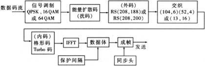
Several optional modes are provided in the modulation and coding process, such as the outer code using high data rate RS208? 200 or high protection rate RS208? 188. This is mainly to provide different priorities and protection levels for different data to achieve the purpose of hierarchical transmission.
The ideal system simulation is mainly to verify the correctness of the system signal transmission process. This design is a digital TV design, so the most intuitive way is to input an MPEG2 code stream to the transmission system, observe the received code stream at the system output and play it with the MPEG2 player, so that you can see the entire data in the ideal system The design of the channel is completely correct. With SPW, it is easy to adjust parameters and replace related modules so that the overall performance of the system is optimal. The corresponding receiving process is the process of decoding, deinterleaving, and demodulation. Which mode to choose and what parameters to use can be simply modified in the design. Constant adjustment of parameters and modules can optimize the overall performance of the system.
It can be seen that DMB-T has a strong forward error correction capability. In theory, the FFT in the receiver using OFDM modulation can smooth out various pulses of short duration, so it should be more robust to pulse interference in the time domain; and the high protection rate RS 208 188 code and 104 2, 52 4 mode interleaving coding also makes DMB-T have strong anti-pulse interference capability.
DMB-T uses OFDM orthogonal multi-carrier modulation and uses a large number of sub-carriers for data transmission. Single-frequency interference will damage a small number of sub-carriers, and the lost data can be easily corrected by error correction coding. So DMB-T also has a strong ability to resist single frequency interference.
Judging by the general comparison standard, the DMB-T has a carrier-to-noise ratio tolerance Eb / No of 7.8 Db for SDTV and 10.8 dB for HDTV in the AWGN channel. The idea of ​​layered transmission is used here, with two different results, but even for HDTV, DMB-T has a more outstanding anti-noise performance.
2 Gaussian white noise AWGN and multipath performance research After establishing an ideal system, it is necessary to add a multipath channel model and corresponding channel estimation and processing modules. Because multipath modeling and channel estimation algorithms are relatively complex, simulation is time-consuming. In addition to the parameter simulation, the simulation of the MPEG2 stream is also done. The simulation interface obtained with SPW is shown in Figure 3.
You can use the mouse to adjust the buttons and scroll bars in the figure to achieve the purpose of interactively adjusting system parameters. The upper right corner of the figure corresponds to the wireless channel multipath model defined by the United States and Europe. Click the corresponding button in the design to add the corresponding multipath model, you can get the corresponding simulation results. For the specified multipath model, the signal-to-noise ratio can be adjusted to observe different simulation results. The user can select the adjustable mulTIpath button in the upper right corner of Figure 3 to set the multipath model arbitrarily and set the multipath parameters in the right half of Figure 3 and complete the corresponding simulation. Figure 3 corresponds to the US standard mpath_b channel model, and the lower left part is the channel estimation result of the system based on the received signal. It can be seen that the two match very well.
In the DMB-T system, the sequence is inserted in the time domain, and the channel impulse response is used to estimate the channel, which affects the data transmission rate by 7%. Gaussian noise and time-varying channels have little effect on this channel estimation algorithm, and because the algorithm has been optimized and improved during the development and design process, this system has outstanding performance in anti-multipath interference The receiving environment is particularly suitable. The simulation results of the system parameters are shown in Figure 4. 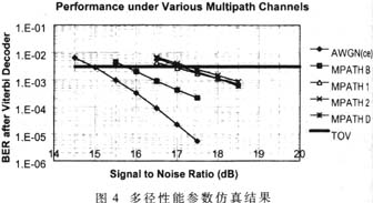
3 System synchronization performance simulation In order to evaluate the synchronization performance of the system, a special synchronization circuit is designed, including transmitter, Code acquisiTIon, STR, AFC, FFT, and Channel EsTImaTIon, etc., which fully realize the system synchronization function. The interactive interface of the simulation is shown in Figure 5. 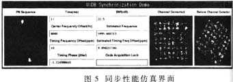
The Time ms field in Figure 5 shows that the actual system running time is different from the simulation time. The following fields represent the frequency offset, time offset, and frequency offset and time offset estimated by the design system synchronization circuit. When capturing the synchronization sequence After "Code Acquisition Lock" field changes from red to green, the right half of the field shows the corresponding constellation before and after channel estimation. From the simulation, it can be obtained that the entire code synchronization acquisition time is only 5ms, which is much shorter than the synchronization time of similar systems. And the correction of time offset and frequency offset have reached the design requirements.
In DMB-T, both the time domain and the frequency domain are used simultaneously.
Sampling clock synchronization, carrier synchronization using spread spectrum pseudo-random PN sequence, signal acquisition time is shortened to 5ms, and time and frequency domain correction can be completed within 20ms, the system achieves synchronization.
4 Design and implementation process In the previous design process, there was no system-level simulation step. Usually, the modification and optimization can only be done after the hardware is completed. The algorithm optimization and parameter adjustment at the system-level level are not only low in cost but also efficient Very high. By continuously adjusting system parameters and improving related algorithms, the optimal performance and theoretical optimal parameters are obtained. As can be seen from the front, the use of SPW software for system-level design and simulation allows designers to focus on the algorithm implementation and optimization of the system, without having to think too much about the specific hardware implementation.
When these system-level simulations are all completed, as shown in the flowchart of Figure 1, the hardware design system HDS of Cadence, Verilog simulation software Verilog-XL and NC-Verilog, SPW and Verilog co-simulation software, etc. The system-level design is converted to RTL-level Verilog hardware description language, which is implemented in FPGA and verified by PCB layout. After field test of the prototype prototype realized by FPGA, the complete design can be made into an application specific integrated circuit ASIC.
Super Silent Yangdong Diesel Generator
Silent Generator For Home Use,Super Silent Yangdong Diesel Generator,Silent Yangdong Generator,Silent Yangdong Diesel Generator
Jiangsu Lingyu Generator CO.,LTD , https://www.lygenset.com