introduction
This article refers to the address: http://
At present, the status quo of a unit in logistics vehicle management is: vehicle scheduling is mainly based on manual control; the identification of internal and external vehicles is based on manual verification and the procedures are cumbersome; the leader cannot control the vehicle in position and scheduling in real time; the dispatching vehicle lacks effective supervision. This kind of management mode has low operating efficiency and insufficient supervision, and it cannot eliminate management loopholes and security risks. After thorough research, we have developed a vehicle network information management system platform, the goal of which is to achieve vehicle management standardization, informationization, security, real-time and high efficiency.
1 system structure
The whole system is mainly composed of the front-end vehicle access control system and the back-end network information management system. The vehicle access control system mainly consists of a long-range passive radio frequency tag attached to the front window of the vehicle, a long-range passive radio frequency card reader, an RF antenna for transmitting and receiving radio frequency signals, a ground-sensing coil, a traffic light, and a server and hardware control function. The computer platform, the remote client and the corresponding control software and other modules. The network information management system is mainly composed of a vehicle information management system and a database management and maintenance system. The vehicle information management system adopts the B/S structure mode, and utilizes the convenience of the network to realize online dispatching, online inquiry of vehicle information, and online maintenance of users and vehicle information. The database management and maintenance system is mainly used to store and retrieve all relevant data information and timely backup and update of important information.
The entire information management platform is mainly composed of a database server, a Web server, and an access control server. It is connected to the existing network within the unit to form a comprehensive information management system integrating identification, control and management. The database server realizes the management and maintenance of basic information such as dispatching vehicle information, vehicle travel information, and user vehicle information; the web server provides online dispatching and information inquiry service; and the control server realizes automatic identification and travel control of the vehicle.
2 Working principle
Vehicle network information management is mainly based on RFID remote passive radio frequency automatic identification technology. Radio frequency identification, commonly known as electronic tags, consists mainly of tags (radio frequency cards), readers (readers or readers) and antennas. The tag consists of a coupling element and a chip, with an internal antenna for communication with the RF antenna. Each tag has a unique electronic code that is attached to the surface of the object to identify the target object. A device that reads and writes tag information from a reader. The antenna transmits RF signals between the tag and the reader. The system uses a passive electronic tag, that is, an electronic tag that has no internal power supply and operates by receiving microwave energy. The effective reading distance of the radio frequency is 7m, and the effective writing distance is 5m.
The workflow of the access control system is shown in Figure 1:
1 The user logs in to the server through the browser to realize online delivery, and the vehicle information is saved in the database;
2 When the vehicle travels (or returns) to the camp gate, the signal sensed by the ground coil is transformed and sent to the control server;
3 The control server starts the RF card reader after collecting the ground sense signal;
4 The radio frequency card reader controls to send a microwave query signal to the radio frequency antenna;
5 The passive RF tag installed on the front glass holds the ID number of the vehicle. After receiving the inquiry signal from the card reader, the tag reflects the data information in the tag back to the card reader according to the command requirements in the inquiry signal. ;
After the card reader receives the microwave synthesis signal reflected by the passive radio frequency tag, the data information stored in the electronic tag is separated by internal demodulation and processing of the card reader;
7 The RF card reader transmits the separated data information to the control server through the RS232/RS485 interface;
8 The control server performs vehicle identification according to the ID number of the received tag data, and queries the dispatch information of the vehicle corresponding to the ID number in the database to determine whether to allow the vehicle to travel. If the vehicle has the right to exit, the door is sent to the retractable door.
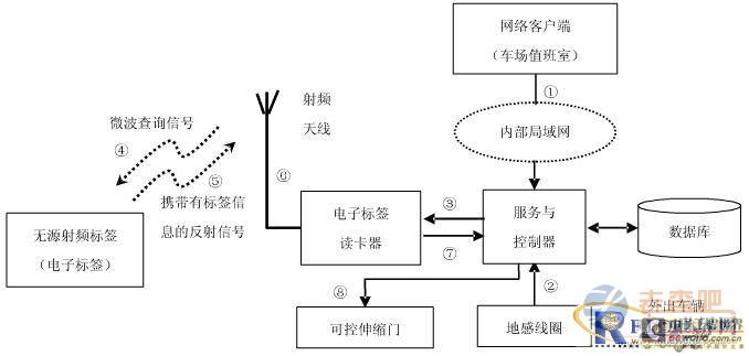
Figure 1 Vehicle access control flow
3 design implementation
3.1 Access Control Design Implementation
The main functions of the access control subsystem are: (1) Automatic detection, identification and judgment of vehicles entering and exiting the gate to determine whether to allow access and automatically control the opening and closing of the telescopic door (or automatic door); Automatically record the entry and exit of the vehicle, take pictures of the entry and exit of illegal vehicles and foreign vehicles for the management department to inquire; (3) perform real-time video surveillance on the scene of the camp gate area; (4) edit the display content of the electronic large screen placard And output control; (5) information query and system management and maintenance.
3.1.1 Hardware components: The hardware of the access control system mainly consists of 1 control host (which can be served by the server), 2 sets of ground sense coil and control circuit, 2 RFID readers and antennas, 1 set of electric gates, and more programmable. The road video capture card consists of 1 block, 2 large-screen electronic display blocks, and 1 data isolation card. The ground sense coil is used for automatically detecting the vehicle entering and exiting the camp gate; the card reader is used for collecting the ID card data attached to the vehicle; the data isolation card is used for the switch state of the ground state, the door gate state, the gate gate control, etc. Signal isolation.
3.1.2 Device Interface: According to the type and characteristics of the selected device, the data transmission between the control host and each device requires two interfaces: parallel and serial. Considering the cost savings, the 2 string 1 (print port) interface provided by the host is directly used, and 2 serial interfaces are expanded as needed. Among them, the assignment of each interface is as follows: PRN, used for the collection of the ground sense coil, the electric gate state, and the switch control of the electric gate and the traffic light.
LPT1, LPT2, after the computer is booted by the system, the initialization process configures the parallel port as two output ports of LPT1 and LPT2, and assigns different data addresses, status addresses and control addresses at the same time. The configuration is shown in Table 1.
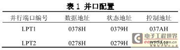
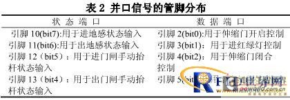
The status port 379H of the parallel port LPT1 performs the acquisition of the state coil and the telescopic electric gate state, and the data port 378H realizes the switch control of the electric gate and the traffic light. The distribution of each pin is shown in Table 2.
COM1, connected to the card reader; COM2, connected to the card reader; COM3, connected to the big screen; COM4, ​​connected to the big screen. All four serial interfaces use the RS-485 interface standard with a transmission rate of up to 56 kBaud and a transmission distance of up to 2 km.
3.1.3 Control implementation
The access control and communication software is programmed by C++Builder, and the database interface is ADO[1]. The control software flow is as follows:
1 Read the PRN status port.
2 The ground state is detected to determine whether there is a traveling vehicle entering the card reading area.
3 Check the state of the grounding state to determine whether the returning vehicle enters the card reading area.
4 Detect the manual lift standard. If there is a manual lift, control the camera to take a photo, and register the guard release record according to the “forbidden signâ€.
3.2 Information Management Design Implementation
The information management interface is implemented in the VBScript scripting language. The information management system is an access interface for end users. It can realize the daily vehicle distribution and information inquiry service of registered users, and can set and modify personal information. Its organizational structure is shown in Figure 2.
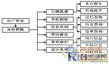
Figure 2 Organizational structure of the information management system
Send Order - After the authorized user logs in to the system, the local or long-distance dispatch command can be issued, and the system automatically generates the dispatch document. The access control system only allows vehicles that have fulfilled the procedures for dispatching vehicles to travel. In-Place Query - Authorized users can check whether the vehicle is in place or not in the unit at any time in the LAN for vehicle scheduling. Travel Enquiry - Authorized users can query the travel status of vehicles, drivers, etc. in any time period, including the time of departure, return time, location of departure, dispatcher, driver and other information. Violation Query - Authorized users can query the violation status record of the vehicle at any time in real time. Password setting - implements the setting and modification of the user password to ensure the security of use. System Management - The administrator can update and maintain the basic information of the registered user information (such as user account, password, authority, etc.), vehicle status, and driver at any time. Information report statistical printing - according to user demand statistics, print various reports.
3.2.1 Logical design of the database
Database management uses SQL Server2000. The data structure adopts index type, that is, one table is responsible for resource indexing, and other tables store the specific content of the resource according to the indication of the index table, which is convenient for adding new projects and reducing the existence of resource garbage, and is convenient for retrieval. The main data logic design includes: (1) vehicle basic information table; (2) driver basic information table; (3) user account relationship table; (4) unit and unit number correspondence table; (5) vehicle dispatching list; 6) Annotation information table; (7) Number information table.
3.2.2 Design of the dispatcher
The access control system controls the opening of the retractable door based on the dispatch document in the database. Therefore, the factors to be considered in the design of the car order are: (1) the date of departure and delivery must be standardized, the storage must be formatted data to facilitate comparison and judgment; (2) the time of departure must be 24 per unit. Within the hour or more than 24 hours (limited to a few days); (3) The dispatched vehicle cannot be in conflict with the vehicle that has already gone out or the vehicle that has sent the vehicle but has not issued the vehicle, otherwise it is considered as Invalid; (4) The out-of-town time of the driver on the departure slip cannot be duplicated with the driver's exit on other dispatched bills, otherwise it will be considered invalid.
3.2.3 System security considerations
System security considerations are all-round and multi-layered, including scripts, databases, servers, etc. In the actual design, we mainly focus on: (1) design identity verification. The first is to verify the user name and password, only legitimate users can log in to the system; the second is to save the user's personal information through the session collection, to prevent users who do not log in correctly from entering the system by specifying the URL. (2) Prevent injection attacks. By filtering illegal characters, it is prevented that the variables are not filtered and detected directly into the SQL statement in the scripting language, thereby achieving the purpose of invading and destroying the database and even the system. (3) Use the database security policy. The password for the database account cannot be too simple, and don't let the password of the account be written in the application or script. Encryption can be done or passwords can be changed periodically. Strengthen the logging of database logs periodically to check for suspicious login events and so on. (4) Strengthen website server security measures. If you install anti-virus software and network firewall, update the virus database and analyze log records in a timely manner to reduce the security risk to a lower level.
4 Conclusion
The system has been developed and put into operation. Its implementation truly fulfills the rules of vehicle management, eliminates loopholes in the management field, improves the accuracy, safety and real-time of management work, and makes the unit's vehicle information management precise and regularized work leap into a new one. Steps.
Vibration speaker:
Vibration speaker is a kind of speaker unit which is made from vibration principle. It is also called resonance speaker. Vibration Speakers have no diaphragms and also called exciters. They drive any solid plane surface they contact and made that surface sound, so people can have original sound from different materials. Vibration speakers have a special penetrability which traditional speakers don`t have. These kind of speakers are mainly used for digital audio speakers, music massage facilities and music treatment facilities.
Our main vibration speakers include:
1) From the diameter: we have speakers in diameter of 18mm ~ 44mm.
2) From the power output, we have speakers of 2W ~ 15W.


FAQ
Q1. What
is the MOQ?
XDEC: 2000pcs for one model.
Q2. What is the delivery lead time?
XDEC: 15 days for normal orders, 10 days for urgent orders.
Q3. What are the payment methods?
XDEC: T/T, PayPal, Western Union, Money Gram.
Q4. Can you offer samples for testing?
XDEC: Yes, we offer free samples.
Q5. How soon can you send samples?
XDEC: We can send samples in 3-5 days.
Vibration Speakers
Vibration Speaker,Vibration Driver,Vibro Speaker,Vibration Bluetooth Wireless Speaker
Shenzhen Xuanda Electronics Co., Ltd , https://www.xdecspeaker.com