The embedded system can quickly calculate, analyze, and output various data information, that is, complete the processing of the data, but often the user needs to "tell" the system how to perform the next action. In this case, the user needs to use the input device to perform the user. The "indication" or "base" is passed to the embedded system.

Common human-computer interaction input devices include buttons, touch screens, microphones, and other types of sensors that can be controlled by users. With the development of technology, not only do our common interactive input devices have new forms, but also a lot of new interactive input methods. For example, the capacitive button and gravity sensing sensor and distance sensor in the mobile phone. Today's interactive devices are not only reflected in the complexity of hardware devices, but also have a large increase in the complexity of related data. For example, a microphone that can be used for voice input and a camera that can be used for face recognition, in order to complete these human-computer interaction inputs, in addition to the hardware input device for information collection, a large amount of data processing is required in the background to help the system "understand" the user. "Enter information".
Below we detail the most commonly used input devices: keyboard / button.
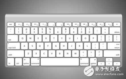
Figure 1 The most commonly used input device keyboard
keyboard
The keyboard is one of the common external devices for embedded applications. The keyboard is a switch matrix consisting of several buttons, which is the simplest digital input device. For the system, the different keys on the keyboard represent different meanings (generally, the meaning of the keys can be defined by software). The user can input simple data and commands by pressing the keys of the keyboard to realize simple human-computer interaction.
1, the basic circuit of the keyboard
The basic circuit of the keyboard is a contact switch, and the on and off states respectively indicate logic "0" and "1". As shown in Figure 2, when the switch is turned on, the processor detects that the corresponding pin is high, indicating logic "1"; when the switch is closed, the processor detects that the corresponding pin is low, indicating logic "0" ".
2, the classification of the keyboard
The key arrangement can be divided into a separate key keyboard and a matrix key keyboard; according to the method of reading the key value, it can be divided into a direct reading mode and a scanning mode; according to the encoding mode, it can be divided into a non-coding mode and Hardware coding mode; according to the microprocessor response mode can be divided into interrupt mode and query mode. The various ways described above combine to form a keyboard with different hardware structures and interfaces. The following two methods are more commonly used.
1 freestanding
The stand-alone key keyboard refers to directly connecting each independent key to the I/O input port of the microprocessor in a one-to-one manner, as shown in Figure 2. When reading a key value, the processor can detect the state of the corresponding I/O input port, determine the input level, and determine the logical value of the input. The buttons are independent of each other in hardware and reading mode, so it is customary to call such buttons as independent buttons. This method is simpler to implement on both hardware and software, but each button occupies an I/O port, which occupies more resources. Generally, it is used when the number of buttons is small and the microprocessor I/O resources are sufficient.
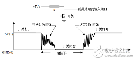
Figure 2 keyboard model and button jitter diagram
2 matrix
The matrix keyboard uses n I/O lines to form a row input port, and m I/O lines constitute a column output port, and a button is set at each intersection of the row and column lines. As shown in Fig. 3(b), it is a matrix keyboard of 4 rows and 4 columns. The matrix keyboard read key value generally adopts the progressive scan mode, that is, the output port rotates and outputs the low level according to the bit rotation, and then reads the information from the input port, and finally calculates the information read from the input port each time to obtain the key code. For example, configure row0~3 as the output mode, and col0~3 as the input mode; now row0 is output low, row1~3 is output high, read col0~3; if at this time, row 0 and column 0 When the button is pressed, col0 detects that the input is low and the other columns are high. This method occupies less I/O lines and is used more in applications with more buttons.
When designing a keyboard, applications that typically have less than 4 buttons can use a stand-alone interface. If you have more buttons, you can use a matrix keyboard to reduce the I/O port usage of the microprocessor.

Figure 3 independent keyboard and matrix keyboard
In addition, if the processor I/O is directly connected to the matrix keyboard interface, the detection mode of the above matrix keyboard requires the processor to continuously scan the interface. For faster processors, this type of detection is a huge waste of processor. Therefore, in practical applications, it is recommended to use a dedicated matrix keyboard driver chip or I/O expansion chip to implement detection of the matrix keyboard, such as ZLG7290, CAT9555 and other expansion chips. Using a driver or I/O expansion chip, the processor can be freed from simple but frequent keyboard scans. Figure 4 shows the basic circuit of the ZLG7290 matrix keyboard application. The chip supports 2 & TImes; 8 I / O extensions, I2C interface and processor connection, and supports interrupt output, maximum scalable 8 & TImes; 8 matrix keyboard.
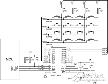
Figure 4 ZLG7290 matrix keyboard circuit
Anyang Kayo Amorphous Technology Co.,Ltd is located on the ancient city-Anyang. It was founded in 2011 that specializes in producing the magnetic ring of amorphous nanocrystalline and pays attention to scientific research highly,matches manufacture correspondingly and sets the design,development,production and sale in a body.Our major product is the magnetic ring of amorphous nanocrystalline and current transformer which is applied to the communication, home appliances, electric power, automobile and new energy extensively. We are highly praised by our customers for our good quality,high efficiency,excellent scheme,low cost and perfect sale service.
Our high frequency transformer is mainly used in high frequency switching power supply as high frequency switching power transformer, also used in high frequency inverter power supply and high frequency welding machine as high frequency inverter transformer. According to the working frequency,it can be divided into several grades:10KHZ-50KHZ,50KHZ-100KHZ,100KHZ ~ 500KHZ,500KHZ ~ 1MHz,and more than 1MHz
High Frequency Transformer,Small And Good Transformer,New Developed Transformer,Useful High Frequency Transformer,Hot Sale Transformer
Anyang Kayo Amorphous Technology Co.,Ltd. , https://www.kayoamotech.com