The working principle of several modes of LCD
1. The liquid crystal material is the main body of the liquid crystal display device. No matter what kind of liquid crystal display is based on the following principle, that is, by the action of an external field such as electric field or heat, the liquid crystal molecules are changed from a specific initial arrangement state to other arrangement states, as the arrangement of liquid crystal molecules changes , The optical characteristics (birefringence characteristics) it exhibits change accordingly, and finally transform into light and dark visual changes.
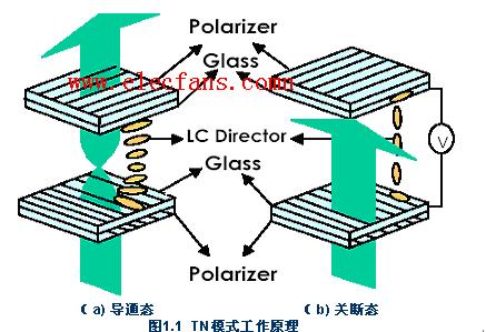
2. The working methods adopted by ordinary TFT active matrix liquid crystal displays are all normally white (Normally White) in TN (Twisted NemaTIc) mode. The most important feature of the TN mode is that the setting of the liquid crystal cell satisfies the Morgan condition (the specific expression is: the product of the twisted pitch of the liquid crystal molecule and its refractive index anisotropy is much greater than half of the wavelength of the incident light, ie Δnd »λ / 2), In this way, when the light passes through the liquid crystal layer, the rotation of its polarization plane is independent of the wavelength, (or when the Morgan condition is met, the angle of rotation of the respective polarization plane of the incident light of different wavelengths after passing through the liquid crystal layer is the same); The liquid crystal cell is filled with Np (positive nematic phase) liquid crystal, the liquid crystal molecules are arranged along the surface, and the long axis of the molecule is continuously twisted by 90º between the upper and lower glass substrates, and the upper and lower polarizers are arranged orthogonally.
The working principle of the TN box is shown in Figure 1.1 below: In the off state, since the Morgan condition is met and the polarization direction of the polarizer is parallel to the director of the liquid crystal molecules at the surface of the lower substrate, the incident ray polarization obtained through the polarizer After entering the liquid crystal layer, it will rotate synchronously with the gradual twist of the liquid crystal molecules (this is called: optical rotation effect). When it reaches the upper substrate, its polarization plane rotates to 90 °, and its polarization direction becomes the polarization of the analyzer The direction of polarization is parallel, so that the linearly polarized light can pass through the analyzer to display a bright state display (because it is a white screen when there is no electric field, it is called "normally white mode"). When we apply a voltage greater than the threshold Vth to the liquid crystal cell, the twisted structure of Np-type nematic liquid crystal molecules will be destroyed and become obliquely aligned in the direction of the electric field; when the applied voltage reaches 2Vth, except for the molecules on the upper and lower substrate surfaces All other liquid crystal molecules become rearranged along the direction of the electric field. At this time, the 90º optical rotation performance of the TN cell disappears, and the liquid crystal cell between the orthogonal polarizers loses its light transmission effect, thereby obtaining a dark state display.
3. At present, there is still the STN mode, which uses the birefringence characteristics of liquid crystal molecules to work (and the above TN mode uses the optical rotation characteristics of the specially set liquid crystal molecular layer to work). Due to the complex process and the color display is not ideal for this mode (there is interference color, that is, the color reproduction ability is not good), so it is only used for low-end display, such as mobile phones, PDAs, etc.
The difference between the STN mode liquid crystal cell and the TN mode is only in the following points: (1) The polarization direction of the polarizer and the long axis of the liquid crystal molecules at the lower substrate (that is, the optical axis direction) are not parallel to each other but at an angle of 30º. In this way, the linearly polarized light obtained by the polarizer will undergo birefringence when it enters the liquid crystal layer. (2) The liquid crystal molecules on the upper and lower substrates are continuously twisted by 270º in the long axis direction, but 90º in the TN cell.
The working principle of the STN mode is as follows: when not powered, the liquid crystal molecules are twisted (the long axis direction of the liquid crystal molecules at the upper and lower substrates is continuously twisted by 270º), because the polarization directions of the liquid crystal molecules and the polarizer at the lower substrate are not parallel to each other but become 30 Angle, so that the linearly polarized light obtained by the polarizer will be birefringent when it enters the liquid crystal layer. The two electric vector components of the refracted light are recombined at the upper plate to become elliptically polarized light, and finally a part of the light Shoot from the analyzer. When power is applied, the twisted structure of the liquid crystal molecules is disintegrated into a vertically aligned state, and the polarizers arranged orthogonally can block the projection of light and obtain a dark state display.
4. In the above two modes, the greater the applied voltage, the greater the tilt angle of the liquid crystal molecules (the closer to the vertical arrangement state), the greater the corresponding transmitted light intensity; the smaller the applied voltage, the smaller the tilt angle of the liquid crystal molecules ( The closer to the state of arrangement along the surface), the smaller the corresponding transmitted light intensity. In other words, by controlling the magnitude of the applied voltage, you can achieve the desired grayscale display.
5. Color display mechanism:
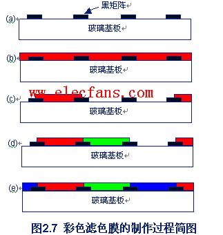
The color display of the current liquid crystal display device is realized by using color filter films. The process of making color filter is shown in Figure 2.7:
The structure of the assembled liquid crystal cell can be seen in the following figure (this is the structure diagram of the MVA mode liquid crystal cell in my graduation design. The TN mode liquid crystal cell only has no upper and lower bumps, the other is basically the same), that is, the color filter The R, G, and B primary colors of the film are arranged in a certain pattern, and correspond to the TFT sub-pixels on the TFT substrate one by one (note: one pixel is composed of three sub-pixels). The white light emitted by the backlight becomes the corresponding R, G, and B colored light after passing through the color filter. Through the TFT array, the voltage value applied to each sub-pixel can be adjusted, thereby changing the transmission intensity of each color light. RGB colors of different intensities are mixed together to achieve color display.
6. There are other modes, such as MVA mode, IPS mode, etc., which are newly developed LCD working modes to improve the viewing angle characteristics and increase the response speed, which is an improvement to the TN mode. 
7. The setting of the upper and lower polarizers (that is, the polarizer and analyzer) determines the light and dark states of the liquid crystal cell under the powered and unpowered state: when the upper and lower polarizers are orthogonally set (that is, the polarizer and the polarizer) When the polarization directions of the analyzers are perpendicular to each other), the TN and STN modes are in a bright state when they are not powered (so they are called normally white mode); when they are powered, they are displayed in a dark state. When the upper and lower polarizers are arranged in parallel (that is, the polarization directions of the polarizer and the analyzer are parallel to each other), the TN and STN modes are dark in the unpowered state (so it is called the normally black mode). Instead, it is bright.
Tourist Car,Tourist Vehicle,Electric Sightseeing Car,Semi-Closed Electric Vehicle
Jinan Huajiang environmental protection and energy saving Technology Co., Ltd , https://www.hjnewenergy.com