1. Design tasks and requirements
1. Design a traffic light control circuit at an intersection, requiring vehicles on lanes A and B to alternately run, with each travel time set to 25 seconds;
2. The yellow light must be on for 5 seconds before changing lanes;
3. When the yellow light is on, it is required to flash once per second.
2. Experimental preview requirements
1. Review the basics of digital system design.
2. Review the working principle of multi-channel data selector and binary synchronization counter.
3. According to the traffic light control system block diagram, draw a complete circuit diagram.
3. Design principle and reference circuit
1. Analyze the logic function of the system and draw its block diagram. The functional block diagram of the traffic light control system is shown in Figures 12 and 1. It is mainly composed of controller, timer, decoder and second pulse signal generator. The second pulse generator is the standard clock signal source of the timer and controller in the system. The decoder outputs the control signals of two sets of signal lights. After the drive circuit, the signal lights are driven to work. The controller is the main part of the system, which controls the timing. And decoder work. In the picture:
TL: It means that the time interval for the green light of lane A or lane B is 25 seconds, which is the time interval for normal traffic of vehicles. When the time is up, TL = 1, otherwise, TL = 0.
TY: indicates that the yellow light is on for 5 seconds. When the time is up, TY = 1, otherwise, TY = 0.
ST: indicates that after the timer reaches the specified time, the controller sends out a state transition signal. It controls the timer to start the timing of the next working state.
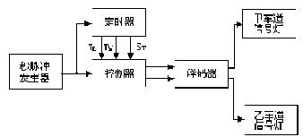 |  |
Figure 12.1 Functional block diagram of traffic light control system | 2. Draw the ASM (Algorithmic State Machine, algorithm state machine) of the traffic light controller |
(1) The green light of lane A is bright, and the red light of lane B is bright. Indicates that vehicles in lane A are allowed to pass, and lane B is forbidden. When the green light is on for a specified time interval TL, the controller sends out a status signal ST to go to the next working state.
(2) The yellow light of Lane A is on, and the red light of Lane B is on. It means that vehicles in lane A that have not passed the parking line stop, vehicles that have passed the parking line continue to pass, and lane B is forbidden. When the yellow light is on for a specified time interval TY, the controller sends out a state transition signal ST to go to the next working state.
(3) The red light of Lane A is on and the yellow light of Lane B is on. Indicates that lane A is forbidden to pass, and vehicles in lane B are allowed to pass when the green light is on for a specified time interval TL, the controller sends a state transition signal ST to go to the next working state.
(4) The red light of Lane A is on and the yellow light of Lane B is on. Indicates that Lane A is forbidden to pass, vehicles on Lane B passing through the county parking line are stopped, vehicles passing the parking line are stopped, and vehicles passing the parking line continue to pass. When the yellow light is on for a specified time interval TY, the controller sends a state transition signal ST, and the system switches to the (1) th working state.
The transition of the four working states above the traffic lights is controlled by the controller. Set the four status codes of the controller as 00, 01, 11, and 10, and use S0, S1, S3, and S2 to represent them respectively. Then the working status and functions of the controller are shown in Tables 12 and 1. , Control signals of red, yellow and green lights in Lane B. For simplicity, the code of the lamp and the driving signal of the lamp are combined into one, and the following provisions are made:
Table 12.1 Controller working status and function control status Signal status Status lane running status S0 (00) A green, B red lane traffic, B lane prohibited S1 (01) A yellow, B red lane A slow, B lane prohibited Passing S3 (11) A red and B green lanes are forbidden to pass, and lane A is passing S2 (10) A red and yellow lanes are forbidden to pass, and lane A slows down AG = 1: the green light of lane A is on;
BG = 1: The green light of Lane B is on;
AY = 1: The yellow light of Lane A is on;
BY = 1: The yellow light of Lane B is on;
AR = 1: The red light of Lane A is on;
BY = 1: The red light of Lane B is on;
The ASM diagram of the traffic light is obtained as shown in Figures 12 and 2. Suppose the initial state of the controller is S0 (S0 is represented by a status box). When the duration of S0 is less than 25 seconds, TL = 0 (TL is represented by a judgment box), and the controller keeps S0 unchanged. Only when the duration of S0 is equal to 25 seconds, TL = 1, the controller sends a state transition signal ST (representing ST with a conditional output box), and transitions to the next working state. By analogy, you can understand the meaning of ASM diagram.
3. The design of the unit circuit (1) The timer is composed of a counter synchronized with the system second pulse (provided by the clock generator). The counter is required to be cleared first under the action of the state signal ST, and then under the action of the rising edge of the clock pulse , The counter increments by 1 from zero, and provides the controller with timing signal TY of mode 5 and timing signal TL of mode 25.
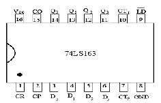
The counter selects the integrated circuit 74LS163 for simpler design. 74LS163 is a 4-bit binary synchronization counter, which has the functions of synchronous clearing and synchronous setting. 74LS163's outer lead arrangement diagram and timing waveform diagram are shown in Figures 12 and 3, and its function table is shown in Tables 12 and 2. In the figure, is the low-level active synchronous clearing input terminal, is the low-level effective synchronous parallel setting control terminal, CTp, CTT are the ASM figure control terminal of the traffic lights in Figure 12, 2 and CO is the carry output End, D0 ~ D3 is the parallel data input terminal, Q0 ~ Q 3 is the data output terminal. The timer circuit composed of two 74LS163 cascades is shown in Figures 12 and 4. Please analyze the working principle of the circuit yourself.
 |  |
(2) Controller The controller is the core of traffic management. It should be able to control the transition of the working state of the traffic lights according to traffic management rules. From the ASM diagram, the state transition table of the controller can be listed, as shown in Tables 12 and 3. Two D flip-flops FF1 and FFO are used as timing registers to generate 4 states. The condition of the controller state transition is TL and TY. When the controller is in the state of Q1n + 1Q0n + 1 = 0, if TL = 0, then control The controller remains in the 00 state; if it does, the controller transitions to the Q1n + 1Q0n + 1 = 01 state. These two cases have nothing to do with the condition TY, so they are represented by an unrelated item "X". The rest of the cases are analogous, and the state transition signal ST is also listed in the table.
Table 12, 2 74LS163 function table
| 
Table 12, 3 Controller state transition table 
According to Tables 12 and 3, the state equations and transition signal equations can be derived. The method is to compare the input or state transition condition variables corresponding to the terms Q1n + 1, Q0n + 1, and ST to 1, where "1" Expressed by the original variable, "0" is expressed by the inverse variable, and then the terms are ORed together to get the following equation: 
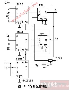
According to the above equation, the data selector 74LS153 is used to implement the input function of each D flip-flop, and the current state value () of the flip-flop is added to the data selection input of 74LS153 as the control signal. The functions of the controller can be realized. The logic diagram of the controller is shown in Figures 12 and 5. In the figure, R and C constitute a power-on reset circuit.
(3) Decoder The main task of the decoder is to translate the four working states of the controller's outputs Q1 and Q0 into the working states of the six signal lights on the lanes A and B. The relationship between the state code of the controller and the signal control signal is shown in Tables 12 and 4. Readers who design the decoding circuit to realize the above relationship should design it by themselves.
4. Experimental equipment
1. Digital circuit experiment box
2. Integrated circuit 74LS74 1 piece, 74LS10 1 piece, 74LS00 2 pieces, 74LS153 2 pieces, 74LS163 2 pieces, NE555 1 piece
3. Resistance 51KΩ 1 pc, 200Ω 6 pcs
4. Capacitor 10Uf 1
5. 6 other light emitting diodes
5. Experimental content and methods
Table 12, 4 Controller status code and signal lamp relationship table
1. Design and assemble the decoder circuit, the output of which is connected to 6 signal lights on the lanes of A and B (replaced by light-emitting diodes in the experiment) to verify the logic function of the circuit.
2. Design and assemble the second pulse generating circuit.
3. Assemble and debug timing circuits. When the CP signal is a 1Hz square wave, draw CP, Q0, Q1, Q2, Q3, Q4, TL. , TY waveform, and pay attention to the timing relationship between them.
4. Assemble and debug the controller circuit.
5. Complete the joint adjustment of the traffic light control circuit and test its function.
6. Experimental report
1. Draw the schematic diagram of the experimental circuit, and indicate the parameter values ​​of each component.
2. Draw the timing waveforms in the experiment, sort out the experimental data, and explain.
3. Write down the fault phenomena and their solutions during the experiment.
4. Answer the thinking questions.
5. Experience and suggestions.
7. Thinking questions Can the counter 74LS161 with asynchronous clearing function be used to replace 74LS163 in the circuits shown in Figures 12 and 4? Explain the reason.
EN: AC220-240V/50Hz, 1000W/2000W Heat setting
US: AC120V/60Hz, 750W/1500W Heat setting
LED lights
one door open
Adjustable flame brightness
Remote control for choice(on/off,heating 1 and heating2)
The origin of the fireplace can be traced back to the time when mankind has just moved into the cave when using the "fire pond" lighting, heating, barbecue food. With the development of productive forces, lighting, heating, barbecue food these three functions gradually evolved and separated.
Fireplaces become dedicated heating equipment: the development of the times, to the fireplace has brought new changes. Morphologically speaking, the fireplace from the traditional firewood fireplace, gas fireplace, charcoal fireplace, etc., and then derived a new category: electric fireplace.
Electric fireplace is a reference to the European classical fireplace production process and modern acoustics principle, so that the traditional fireplace in the design has been greatly improved, in the elegant yet created a green and more bruised real wood burning effect.
Electric Fireplace
Electric Fireplace, European Style Electric Fireplace, LED Fake Flame Electric Fireplace, Wall Mounted Electric Fireplaces
Ningbo APG Machine(appliance)Co.,Ltd , http://www.apgelectrical.com