Today, the electromagnetic compatibility (EMC) of electronic and electrical products is increasingly valued by countries around the world, especially in developed countries such as Europe and the United States. In China's 3C certification also has an important content: EMC testing.
There are still many people who are not profoundly understanding the concept of electromagnetic compatibility. Some of the problems encountered in the EMC area are not known, and I do not know where to start improving. I have been engaged in the development of electronic products. In recent years, I have also engaged in the development and management of LED power. I have accumulated a little bit of experience and I share with you here.
First look at what is electromagnetic compatibility:
Electromagnetic compatibility is a science that studies the use of various electrical devices or systems that can coexist within a limited space, limited time, and limited spectrum resources, without causing performance degradation. In layman's terms, a qualified electric device or system that emits electromagnetic interference during work should comply with the standard (that is, below a certain amount), and the ability to resist interference should also comply with the standard (ie, higher than a certain amount). ).
There are mainly two ways to spread electromagnetic interference: one is space emission (radiation interference), and the other is power line conduction (conducted interference).
Electromagnetic compatibility test is divided into interference (EMI) test and anti-interference (EMS) test.
In the interference phenomenon of electronic equipment, the electromagnetic interference effect is not only related to the amplitude of the pulse but also related to the repetition frequency of the pulse. In other words, even if the amplitude of the interference pulse is large, the frequency of interference is limited when the frequency is low. On the contrary, the frequency of the interference pulse is high, but the amplitude is small, so its interference ability is also Smaller. Therefore, to measure the interference effect of interfering pulses, it is necessary to consider both the amplitude of the pulse and the repetition frequency of the pulse. Therefore, in the EMI test, the quasi-peak value is often used instead of the peak value to measure whether the product under test is qualified.
In the EMI test, the following three values ​​are mainly tested:
Peak - The maximum value of the period of the interference pulse is the amplitude described above.
Quasi-peak - The detected value with a specified time constant is not only related to the amplitude of the pulse but also related to the repetition frequency of the pulse.
Mean - The average size of the interfering pulse in the period, which is mainly dependent on the repetition frequency of the pulse.
Here are examples to share my EMC rectification experience:
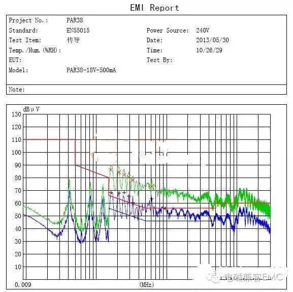
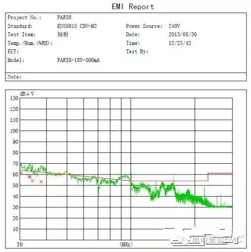
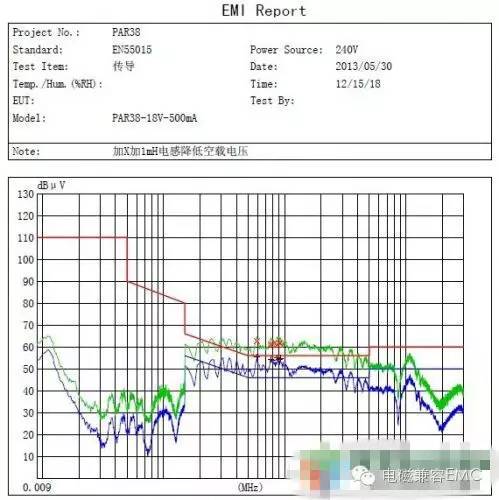
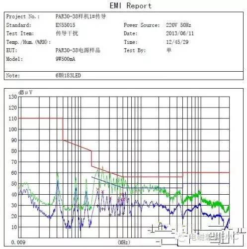
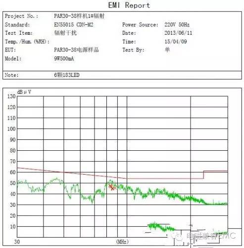
Please see the above two diagrams: This is an LED power supply for the PAR38 that was done by an engineer of our company. Because the company did not require EMC testing at the beginning, the components that can be saved are saved. Later, the engineer left the company and the company requested that this power source pass the CE certification. I took a sample to test EMI, and the conducted and radiated interference were significantly exceeded.
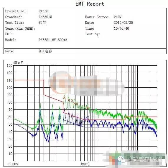
So, I improved this, first of all to improve the conduction interference, because the conduction interference is transmitted through the power line, so add the filter inductor and X capacitor at the input end of the power supply, because it is a built-in power supply, small size, plus 2 1mH The I-shaped inductor and a 0.1UF X capacitor, the following two figures are improved test results:
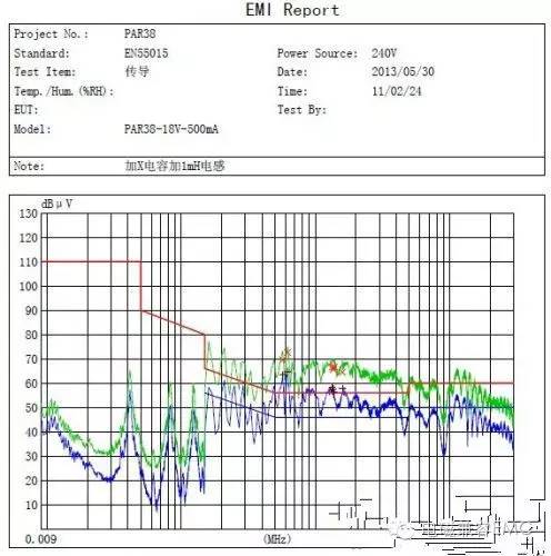
The improvement effect is not very good, through the test found that its output no-load voltage is much higher than the actual output voltage, so I reduced the no-load voltage, test again, and improved, see the figure;
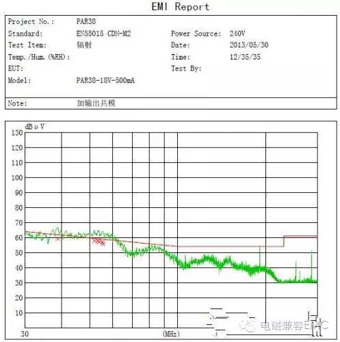
At this point, the use of brains in conduction is no longer effective, and the space is limited. It is impossible to add too many or too many components. At this time, the radiation is still exceeding the standard. If the radiation is qualified, the conduction will be improved. So, I turned to improve the radiation problem. First add the transformer to the outer shield, and at the same time add a 200UH magnetic ring common-mode inductor at the output end. After testing, the radiation has improved a lot.
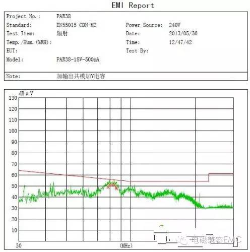
To meet the requirements, a 102 Y capacitor was added between the primary and secondary sides.
At this time, the conductivity was measured again and it has been greatly improved, but it is still a little bit worse. Please see the following figure:
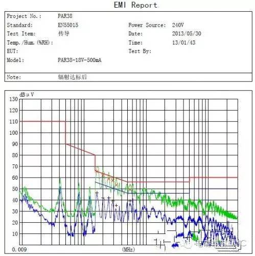
After this improvement, it has basically met the requirements. Then, I redraw the schematic diagram, add all the components used, add an absorption circuit to both ends of the output rectifier diode, and re-adjust the PCB layout, and change the original dual panel to Single panel, after more than one week, the PCB of proofing came back, and then several prototype tests were done and all were up to standard.
It can be seen from this example that EMC's rectification is actually not as difficult as it seems. If you understand its principles, find out the root cause, and apply the right medicine, you will certainly be able to make a qualified power supply.
Wire harness and the surrounding parts shall be even and sufficient distance shall be kept from the heat source,
Considering the protection against electromagnetic interferencee,
Consider assembly technology, maintenance technology,
Grounding wire layout,
Heat dissipation of wire harness and fuse box
Car Seat Harness,Power Seat Wiring Harness,Power Seat Harness,Right Seat Wire Harness
Dongguan YAC Electric Co,. LTD. , https://www.yacentercn.com