0 Foreword
With the continuous improvement of the living standards of our people and the increase in electricity consumption, electrical fires have also increased dramatically, which has also caused huge losses to the national economy and people ’s lives and property. According to the "China Fire Statistics Yearbook", electrical fires rank first in the number of fire accidents in recent years, and the proportion accounts for 30%, and the trend is increasing year by year, causing heavy losses. In fact, electrical fires have become the main disaster-causing factor for fire safety. Not only are they more frequent and have more losses, but they have also remained high for many years.
The main causes of electrical fires in public buildings are as follows:
0.1 The conductors in the building are in disrepair after years of use, and their insulation layer is damaged due to aging.
0.2 The installation and construction of the wires in the building are not standardized. For example, if the wires do not pass through the pipeline protection, they are directly buried in the wall or placed on the component.
0.3 During the second decoration of entertainment venues and other public event venues, wires are laid randomly, resulting in hidden fire hazards.
0.4 The quality of the conductor construction is rough, cut corners, and the use of steel pipe threading is to insulate the wire insulation layer on the inner wall of the steel pipe.
0.5 The circuit is affected by natural conditions, such as air humidity causing the insulation level of the conductor to drop.
In view of the above aspects, Ankerui Electric Co., Ltd. developed the Ankerui Acrel-6000 based on its self-developed ARCM series electrical fire monitoring detectors, through the integration of RS485 bus technology and terminal computer software display technology / B Electrical fire monitoring system. While displaying the data of each detection point, the background of the system also provides functions such as over-limit sound and light alarm and humanized interface. The system realizes 24-hour unmanned real-time monitoring of the power distribution system, reduces labor costs, and improves the efficiency of eliminating electrical fire hazards.
This article briefly introduces the practical application and practical significance of the Ancorui Acrel-6000 / B electrical fire system on the application of the electrical fire system in the production supporting project of Yutong Energy Saving and New Energy Bus Production Base.
1 Project Overview
Yutong Energy-Saving and New Energy Bus Production Base production supporting project is located in Yutong Industrial Park, Zhengzhou City, Henan Province, east of Qiancheng Road and north of Hongri Road, about 100 meters. Total construction area: 27167.88 square meters, building layers: 2 underground floors, above ground 12 storeys; building height: 67.65m. Building fire classification: first class building, fire resistance level: first class. Main structure type: frame shear structure, use function: underground for parking garage and equipment room, one to twelve storeys for offices. A class of high-rise office buildings.
The project is divided into administrative office building, canteen, R & D center and underground garage. .
Our company selects residual current electrical fire detector ARCM300L-J1, residual current electrical fire monitoring equipment and electrical fire monitoring system Acrel-6000 for the project. The system has the functions of centralized scheduling, control, protection, monitoring, display, etc. It has the advantages of intelligent power management, control, protection, analysis, and recording in one integrated intelligence, which can greatly reduce the incidence of electrical fires in application occasions.
Configure a set of wall-mounted electrical fire monitoring host in the fire control room, and upload the data of the administrative office building, canteen and R & D center to the background monitoring host in the fire control room.
According to the characteristics of this project, in order to prevent electrical fires caused by ground faults, combined with the importance of this project, all lighting and power distribution systems of this project are equipped with leakage fire alarm systems. The system mainly includes the system host, field monitor and data centralized controller. The leakage fire alarm host is set in the fire control room. The system sets a leakage fire detector on the incoming line of the distribution box of the shaft on each floor to monitor the leakage current at this place. When the leakage current of the distribution circuit is greater than 300mA and the working current exceeds the alarm value set by the time limit, it will be The sound and light alarm signal accurately reports the address of the fault point, monitors the change of the fault point, displays its status, and only gives an alarm signal to the power circuit of the device, without cutting off its power supply.
2 Reference standard
In view of the fire in public buildings is easy to cause loss of life and property. In order to increase the intensity of electrical fire monitoring and prevention, in recent years, the state has successively formulated or revised a number of relevant standards and specifications. The relevant standards and specifications have already put forward specific requirements for the electrical fire monitoring system. The design reference standards of the Acrel-6000 / B electrical fire system selected in this project are mainly:
2.1 GB50045-95 (2005 edition) "Code for Fire Protection Design of High-Rise Civil Buildings", which stipulates in Article 9.5.1: High-rise buildings with high fire risk and dense personnel should be equipped with leakage fire alarm systems.
2.2 The relevant provisions of the national standard "Prevention and Testing Methods for Electrical Fires in Buildings" also clearly require that "a residual current action protector that automatically cuts off the power supply or alarms should be installed at the power inlet end.
2.3 The products of the electrical fire monitoring system should meet: GB14287.1-2014 "Electrical Fire Monitoring Equipment", GB14287.2-2014 "Residual Current Type Electrical Fire Monitoring Detector", GB14287.3-2014 "Temperature Measuring Electrical Fire Monitoring" detector"
2.4 The installation and operation of the electrical fire monitoring system should meet GB13955-2005 "Installation and Operation of Residual Current Action Protection Device"
2.5 The power supply of the electrical fire monitoring system should meet the requirements of GB50052 "Code for Design of Power Supply and Distribution System"
2.6 The design of the electrical fire monitoring system shall meet the requirements of "Design Method of Electrical Fire Monitoring System" (provisional regulations)
3. System architecture and design
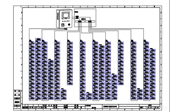
Topology diagram of electrical fire monitoring system
3.1 Station Control Management
The station control management layer is the direct window of human-computer interaction for the management personnel of the electrical fire monitoring system, and it is also the uppermost part of the system. The host of Ankerui electrical fire monitoring system fully considers the user's operating habits and continuous and stable operation, referring to the corresponding national standards and specifications. The host is mainly composed of monitoring software, touch screen, UPS power supply, printer and other equipment. Calculate, analyze, and process all kinds of data information on the scene, and respond to terminal management personnel with graphics, digital display, sound, indicator lights, etc. It enables managers to grasp the system dynamics in real time, and realize the functions of failure information tracking and information export.
In view of the scale of the instrument points and data volume in this project, the Acrel-6000 / B mainframe is now configured for the project. The specific parameters of this mainframe are described below.
3.2 Network communication layer
All instruments in this project must be connected strictly in hand-in-hand form, and all communication buses must be laid along the weak current bridge. The instruments of this project are distributed in the power distribution cabinet of the strong room on the floor.
The data bus of this project is designed as two buses. The independent bus is convenient for later system maintenance. When a leakage current alarm occurs, the fault loop can be quickly located and quickly eliminated according to the check table provided by us later.
On-site electrical fire detectors are connected by hand in hand via twisted pair (ZR-RVSP2 * 1.0), and the number of instruments per bus is less than 30.
3.3 Field device layer
This project is mainly to install the Ankerui rail electric fire detector ARCM300L-J1 for the incoming circuit of the floor distribution box, and to monitor the leakage current of the distribution circuit in real time through the rail electric fire detector to display the entire distribution system Working status.
The ARCM series of residual current electrical fire monitoring detectors are designed for TT and TN systems below 0.4kV. By monitoring and managing the fire hazard parameters such as the residual current of the distribution circuit and the temperature of the conductors, electrical fires are prevented. , And real-time monitoring of multiple power parameters, to provide accurate data for energy management. The product adopts advanced micro-controller technology, high integration, small size, easy installation, intelligent, digital, and network. It is an ideal choice for building electrical fire prevention monitoring, system insulation aging prediction, etc. The product meets the standard requirements of GB14287.2-2014 "Electrical Fire Monitoring System Part 2: Residual Current Type Electrical Fire Monitoring Detector".
4 System characteristics and working principle
In view of the scale of the project, the actual situation of the project's electrical fire detection points. Both the residual current detector at the terminal and the background host are designed according to the actual situation of this project.
4.1 The system characteristics of this project can be summarized as follows:
4.1.1 The terminal detector adopts panel-type electrical fire detector, which is convenient for installation, cost saving, and convenient for later maintenance.
4.1.2 RS485 bus connection is convenient and operable. When the bus is wired, the weak electric bridge is taken, which will not be affected by the strong current, and the communication of the entire system is ensured to be stable.
4.1.3 Considering the amount of instrument data in this project, customer requirements. The host of this project is wall-mounted. The wall-mounted host interface is simple and the system is easy to operate. It is suitable for the distribution room environment in this project and the relevant operational requirements of customers.
4.2 Working principle of electrical fire system
4.2.1 The residual current measurement is based on Kirchhoff's current law: at the same time, the sum of current vectors flowing into and out of a node in the circuit is zero. Taking the TN-S system as an example, A / B / C / N is simultaneously passed through the residual current transformer. When there is no leakage in the system, the sum of the current vectors flowing into and out of the residual current transformer is zero. At this time, the residual current The secondary current induced by the transformer is also 0; when a certain earth leakage occurs, the current vector sum flowing into and out of the residual current transformer is no longer zero, and its magnitude is equal to the current flowing from the earth, that is, the leakage current. This leakage signal is transmitted to the electrical fire detector through the secondary wiring of the residual current transformer, and is sent to the CPU after operation amplification and A / D conversion. After a series of algorithms, the amplitude of the change is analyzed, judged, and The alarm setting value is compared. If the setting value is exceeded, an audible and visual alarm signal is issued and sent to the background electrical fire monitoring equipment.
4.2.2 The terminal detector is responsible for monitoring the residual current value of each loop and transmitting the data of the residual current value to the system host. The terminal detector is also responsible for the real-time display of the residual current value of its monitoring loop, and at the same time can set the limit value. When the residual current value exceeds the limit, it can emit an audible and visual alarm to remind the management personnel to maintain and rectify in time.
4.2.3 The instrument transmits the data to the system host through the RS485 bus, and the system host will reflect the running status of the entire system through graphics, reports, event records, etc.
5 System design considerations and methods
5.1 The electrical fire monitoring system mainly monitors two types of objects: residual current and temperature. Basic points to be noted when designing
5.1.1 About residual current
Because the principle of residual current monitoring adopts Kirchhoff's current law, there are certain requirements for the form of the applied low-voltage power distribution system. At present, low-voltage power distribution systems that can use residual current transformers are: TT system, IT system, TN-S system, which cannot be used in TN-C system. For users who will design and install electrical fire monitoring systems, whether it is a new project or an old project renovation project, first investigate and verify what the system grounding form of the user ’s low-voltage distribution system is, otherwise, design and install residual current transformers. Detection is simply impossible.
Regarding the AC220V single-phase power supply system, the residual current transformer only needs to cover the L / N two power lines, but the neutral line N is not allowed to be grounded thereafter. For the AC380V three-phase power supply system, due to the use of three-phase three-wire system, three-phase four-wire system, three-phase five-wire system, etc., the residual current transformer will be sheathed on the A / B / C three-phase power line at the same time, Or trap the A / B / C / N line at the same time. Similarly, it is required that the neutral line N is not allowed to be grounded again, and the protection line PE must not pass through the transformer.
When the form of system grounding is TN-C type, the industrial automation network must be transformed into TN-S type, TN-CS type, or local TT type system before installing the residual current detection device.
5.1.2 About temperature
Temperature measurement has nothing to do with the form of system grounding. It mainly considers the temperature of key parts in low-voltage power distribution equipment including cables, and is generally used in secondary protection circuits. The temperature probe Pt100 can adopt the contact arrangement method. When the detected object is an insulator, the temperature sensor of the detector should be directly placed on the surface of the detected object. When the detected object is the temperature change inside the power distribution cabinet, a non-contact arrangement can be adopted, close to the heat-generating components.
5.2 Point allocation in system design
According to the provisions on classification protection in Article 4.4 of National Standard GB13955-2005 "Installation and Operation of Residual Current Action Protection Device", the steps of the principle of point allocation when installing a residual current fire monitoring device are:
5.2.1 Study and analyze the relevant drawings of the controlled low-voltage AC380V distribution line, investigate and verify the distribution of building electrical, determine the location of power distribution equipment (such as power distribution cabinets, boxes, trays, cables and other important equipment), and put each Monitoring detectors are allocated to the corresponding power distribution equipment to determine the number of detectors and avoid wasteful resetting.
5.2.2 Determine hierarchical protection. In order to reduce the scope of power outages caused by personal electric shock accidents and ground faults when the power is cut off, three-level (or two-level) residual current protection devices of different capacities are usually installed at different locations of the power supply line to form graded protection. According to the power load and line conditions, it is generally divided into two or three levels of protection, which is suitable for the first and second level protection in urban and rural areas.
Among them, important lines should include security, firefighting, emergency power, channel lighting lines, and important places that do not allow power outages.
5.2.3 In the second-level protection, all switches must be equipped with residual current fire monitoring detectors, that is, both the power supply end of the line (first-level protection) and the branch first end (the second level is also called end protection). Install the residual current detector and connect it to the electrical fire monitoring system for fire monitoring and alarming purposes only.
5.2.4 The temperature detection is based on the basic principle of heat generation when the power distribution equipment is abnormal.
1) Transformer low-voltage side outlet terminal, transformer body temperature (wind temperature, oil temperature, water temperature) test point, load switch contact.
2) Incoming and outgoing busbar contacts of each power distribution cabinet (box), contacts of automatic switches (circuit breakers, knife switches), concentrated parts of high-current wires, and cable connection points.
3) Main contact of female cabinet and knife switch contact.
4) Compensation capacitor connection terminals and transfer switch contacts.
5.2.5 According to the total number of installation points, select the corresponding wall mount.
6 Configuration of system parameters
6.1 Setting range of alarm value
In this project, the residual current alarm value of the field instrument is set at 600mA, and the setting of the residual current value is specified in the relevant national standards.
According to the regulations in the national standard GB14287.2-2014, the alarm value of the residual current type electrical fire monitoring detector is set in the range of 20 ~ 1000mA. According to this requirement, the residual current action value of the main power supply line is generally set to 400 ~ 800mA, and the residual current action value of the power supply branch line is set to 100 ~ 400mA. Generally, the residual current type electrical fire monitoring and detection is set The alarm value of the device should be not less than twice the maximum value of the leakage current of the protected electrical circuit and equipment during normal operation, and not more than 1000mA. The alarm setting value of the electrical fire detector should consider the normal leakage current of the power distribution system and electrical equipment.
6.2 Regarding the setting reference of the cable temperature rise alarm, according to the regulations on the cable temperature according to the "Code for Design of Power Cables"
6.2.1 High temperature place above 60 ℃ should be subjected to high temperature and its duration and type of insulation requirements, heat-resistant polyvinyl chloride, cross-linked polyethylene or ethylene-propylene rubber insulation and other heat-resistant cables should be selected. Insulated cable. It is not suitable to use ordinary PVC insulated cables in high temperature places.
6.2.2 The ambient temperature of the continuous permissible current-carrying capacity of the cable shall be determined according to the multi-year average of the meteorological temperature in the area of ​​use and shall comply with the regulations. When laying indoor cable trenches, the ambient temperature is the average of the daily maximum temperature of the hottest month of the place plus 5 ° C.
6.2.3 The temperature rise of the cable is related to the laying and heat dissipation conditions.
7 Main equipment parameters
The production supporting project of Yutong Energy Saving and New Energy Bus Production Base is composed of electrical fire monitoring device Acrel-6000 / B and leakage fire detector ARCM300L-J1 leakage current transformer AKH-0.66L.
7.1 Main technical parameters
7.1.1 Power supply: 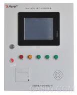
â‘ Rated working voltage AC220V (-15% ~ + 10%)
② Standby power supply: When the main power supply is under voltage or power failure, maintain the working time of monitoring equipment ≥ 4 hours
7.1.2 Working system:
24-hour working system
7.1.3 Communication method:
RS485 bus communication, Modbus-RTU communication protocol, transmission distance 1.2km, can be extended by repeater
Communication transmission distance
7.1.4 Monitoring capacity:
â‘ The monitoring equipment can monitor up to 1024 (must be customized) monitoring units (detectors)
â‘¡ Can be connected with ARCM series monitoring detector
7.1.5 Monitoring alarm items:
â‘ Residual current fault (leakage): fault unit attribute (part, type)
â‘¡ Temperature alarm (over temperature): fault unit attribute (part, type)
â‘¢ Current fault (overcurrent): fault unit attribute (part, type)
Monitoring alarm response time: ≤30s
Monitoring alarm sound pressure level (A weighting): ≥70dB / 1m
Monitoring alarm light display: red LED indicator, red light alarm signal should be maintained until manual reset
Monitoring alarm sound signal: can be manually eliminated, when there is an alarm signal input again, it can start again
7.1.6 Fault alarm items:
â‘ The communication cable between the monitoring device and the detector is broken or short-circuited
â‘¡ The main power supply of the monitoring equipment is under-voltage or power-off
â‘¢ The connection line between the charger that charges the battery and the battery is broken or short-circuited
Fault alarm response time: ≤100s
Monitoring alarm sound pressure level (A weighting): ≥70dB / 1m
Monitoring alarm light display: yellow LED indicator, yellow light alarm signal should be maintained until troubleshooting
Fault alarm sound signal: can be manually eliminated, and when there is an alarm signal input again, it can be started again
During the fault, the normal operation of the non-faulty circuit is not affected
7.1.7 Control output:
Alarm control output: 1 set of normally open passive contacts, capacity: AC250V 3A or DC30V 3A
7.1.8 Self-check items:
â‘ Indicator light inspection: alarm, fault, running, main power, backup power indicator
â‘¡ Check the display
â‘¢ Sound device inspection
Self-checking time ≤60s
7.1.9 Event record:
â‘ Record content: record type, occurrence time, detector number, area, fault description, and can store no less than 20,000 records
â‘¡ Record query: query according to the date, type and other conditions of the record
7.1.10 Operation classification:
â‘ Daily duty class: real-time status monitoring, event record query
â‘¡ Monitoring operation level: real-time status monitoring, event record query, remote reset of the detector, equipment self-check
â‘¢ System management level: real-time status monitoring, event record query, remote reset of the detector, device self-check, system parameter query of the monitoring device, individual detection of each module of the monitoring device, addition and deletion of operators
7.1.11 Operating environmental conditions:
â‘ Workplace: Fire control room, manned transformer substation (distribution room), manned room on the wall
② Working environment temperature: 0 ℃ ~ 40 ℃
③ Relative humidity of working environment: 5% ~ 95% RH
④ Altitude: ≤2500m
7.2 Basic functions
7.2.1 Monitoring alarm function:
The monitoring equipment can receive the leakage and temperature information of multiple detectors, and emit an audible and visual alarm signal when an alarm is issued. At the same time, the red "alarm" indicator on the device lights, the display indicates the alarm location and alarm type, and records the alarm time. Until the detector is reset remotely by pressing the "Reset" button on the display. The audible alarm signal can also be manually eliminated using the "Mute" button on the display.
7.2.2 Fault alarm function
Communication failure alarm: when a communication failure occurs between the monitoring device and any connected detector, the corresponding detector in the monitoring screen displays a fault prompt, and at the same time the yellow "fault" indicator on the device lights up and emits a fault alarm sound .
Power failure alarm: when the main power supply or the backup power supply fails, the monitoring equipment also sends out audible and visual alarm signals and displays the fault information. You can enter the corresponding interface to view detailed information and remove the alarm sound.
7.2.3 Self-test function
Check whether all status indicators, display screens and speakers in the device are normal.
7.2.4 Alarm record storage query function
When a leakage, over-temperature alarm or communication, power failure occurs, the alarm location, fault information, alarm time and other information are stored in the database, and when the alarm is lifted and the fault is eliminated, it is also recorded. Historical data provides a variety of convenient and fast query methods.
7.2.5 Power function
When the main power supply fails, such as power failure, undervoltage, etc., the monitoring equipment can automatically switch to the standby power supply. When the main power supply resumes normal power supply, it automatically switches back to the main power supply. During the switching process, the monitoring equipment is continuously and smoothly operated.
7.2.6 Control function of the detector
Through the monitoring software operation, all the detectors connected to the device can be remotely reset and controlled.
7.2.7 Permission control function
In order to ensure the safe operation of the monitoring system, the operating authority of the monitoring equipment software is divided into three levels, and operators of different levels have different operating authorities.
Conclusion
In summary, the leakage fire alarm system can accurately detect the faults and abnormal conditions of electrical circuits, and can find hidden fire hazards of electrical fires, and promptly alert personnel to eliminate these hidden hazards. From the perspective of building safety, the design of the building leakage fire alarm system is a very important content. In the long run, the leakage fire alarm system can be used as a subsystem in the automatic fire alarm system, so as to realize the combination of strong and weak current optimization in a true sense, and form a perfect automatic fire alarm system.
references
[1]. Ren Zhicheng Zhou Zhong. Principles and Application Guide of Electric Power Measurement Digital Instruments [M]. Beijing. China Electric Power Press. 2007. 4
[2] .Zhou Zhong. The application of electric power meters in the itemized measurement of electric energy in large public buildings [J]. Modern Building Electric 2010. 6
[3]. Shenyang Fire Research Institute, Ministry of Public Security. GB 50116-2013 Design Code for Automatic Fire Alarm System [S]. Beijing: China Planning Press, 2014
[4]. Fire Bureau of Ministry of Public Security. Practice of fire safety technology [M]. Beijing: Machinery Industry Press, 2014.
About the author: You Xiaoyun, female, undergraduate Ankerui Electric Co., Ltd., the main research direction is smart grid power supply and distribution Email: Mobile QQ
Low Rate Nicd Battery KPL Series
Established in 1956, during the China first five-year-plan, Henan Xintaihang Power Source Co., Ltd. (Factory No.755) was the first R&D and manufacturing enterprise in China in the field of alkaline storage batteries and modular power system and it was also the military factory which owned the most varieties rechargeable batteries in domestic. Taihang was located in national Chemistry and Physicals Power Source Industrial Park, Xinxiang City, Henan, China.
Low Dishcharge Rate Nickel Cadmium Battery, KPL10~KPL1200, Max. discharge current <0.5C.
The nickel–cadmium battery (NiCd battery or NiCad battery) is a type of rechargeable battery using nickel oxide hydroxide and metallic cadmium as electrodes. The abbreviation NiCd is derived from the chemical symbols of nickel (Ni) and cadmium (Cd).
Ni Cd Battery,110V Kpl 300Ah Battery,Kpl1000Ah Nicd Battery,Low Rate Nicd Battery Kpl Series
Henan Xintaihang Power Source Co.,Ltd , https://www.taihangbattery.com