Author: NingHeChuan (Ning river)
Foreword: The state machine is good, and the state machine can realize almost all sequential logic circuits.
Finite State Machine (FSM), according to whether the output of the state machine is related to the input, can be divided into Moore type state machine and Mealy type state machine. The output of the Moore type state machine is only related to the current state and the Mealy type state machine is not only related to the current state, but also related to the input, so it will be interfered by the input, and the phenomenon of Glith may occur, so we usually use Moore Type state machine.
State machine coding, binary coding (Binary), Gray code coding (Gray-code), one-hot code (One-hot). The different encoding methods are to prevent mutations in the state transition, making the state transition more stable and the system more reliable, but usually we directly use binary encoding unless the system has special requirements for stability and state encoding.
The description of the state machine, one-stage, two-stage, three-stage.
A one-stage state machine that mixes combinational logic and sequential logic together. This kind of writing can still be used for a state machine with simple logic, but it is not recommended for complex logic. If the state is complex, it is easy to make mistakes, and Too many signals in an always block is also not conducive to maintenance and modification.

// State parameter declaration
parameter S0 = 4'b0000,
S1 = 4'b0001,
s2 = 4'b0010;
// FSM one segment
reg [3: 0] state;
always @ (posedge clk or negedge rst_n) begin
if (! rst_n)
state 《= S0;
else begin
case (state)
S0:
S1:
S2:
.
.
.
default:
endcase
end
end
The two-stage state machine is also a commonly used writing method, which distinguishes combinational logic from sequential logic. The first stage is responsible for state transfer, and the second stage is combinational logic assignment. Common problems such as the occurrence of glitches. The reason why combinatorial logic is more prone to glitches will be mentioned below.
// State parameter declaration
parameter S0 = 4'b0000,
S1 = 4'b0001,
s2 = 4'b0010;
// FSM two segment
reg [3: 0] pre_state;
reg [3: 0] next_state;
// --------------------------------------
// FSM one
always @ (posedge clk or negedge rst_n) begin
if (! rst_n)
pre_state << = S0;
else
pre_state << = next_state;
end
// FSM two
always @ (*) begin
case (pre_state)
S0:
S1:
S2:
.
.
.
default :;
endcase
end
The three-segment state machine can better solve the shortcomings of a two-stage one. I also recommend the writing method. The first stage uses sequential logic for state transfer, the second stage combinational logic is responsible for data assignment, and the third stage sequential logic is responsible for output. The code level is clear and easy to maintain. The output of sequential logic solves the glitch problem of combinational logic in the two-stage writing method. However, the resource consumption will be more. In addition, the three-stage mode will be delayed by one clock cycle from the one-stage and the two-stage mode. When writing a state machine, be sure to design a state transition diagram in advance, taking all states into consideration, to avoid the state from entering an endless loop, or jumping to a deviated state.
// State parameter declaration
parameter S0 = 4'b0000,
S1 = 4'b0001,
s2 = 4'b0010;
// FSM three segment
// --------------------------------------
// FSM one
always @ (posedge clk or negedge rst_n) begin
if (! rst_n)
pre_state << = S0;
else
pre_state << = next_state;
end
// FSM two
always @ (*) begin
case (pre_state)
S0:
S1:
S2:
.
.
.
default :;
endcase
end
// FSM three
always @ (posedge clk or negedge rst_n) begin
if (! rst_n)
dout << = 'b0;
else begin
case (pre_state)
S0:
S1:
S2:
.
.
.
default :;
endcase
end
end
As shown below, I use an example to illustrate the use of state machines. The following is a sequence detection state transition diagram. The detection is to use the sequence 1101. The detection sequence we gave to this sequence is 11101 1101. In this sequence detector, we allow the use of repeated bits. In other words, the 1 in the last bit of the previous "1101" can be used as the start bit of the next "1101" sequence. If repetition is not allowed, just replace S4 to S2 with S4 to S1.
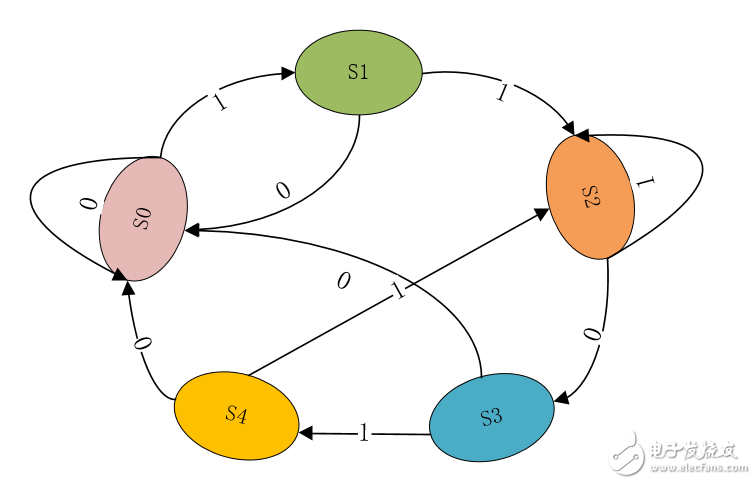
First, start detection from the output state S0, jump to S1 when S0 detects 1, otherwise jump back to S0, S1 detects 1 state to S2, otherwise jump back to S0, S2 detects 0 state to S3, otherwise stay In the S2 state, because our detection sequence allows repeating bits, the 1 detected by S1 and the 1 detected by S2 are retained, and the first two digits of the group 1101 are not discarded, so only need to continue to detect the next bit . The states of S3 and S4 can be deduced by analogy. Here is an example to illustrate the state jump of the state machine, which is also encountered in our actual design.
When using a state machine to describe a sequential circuit, the first thing you should do is to draw a state transition diagram, then describe the code according to the state jump, and finally you will do more with less. I also posted the code for this sequence detection. Of course, this is just an application of sequence detection. I also said earlier that state machine opportunities can implement all sequential circuits. If you encounter a design that is really difficult to solve, then this time, you can consider using a state machine.
module state (
input mclk,
input rst_n,
input din,
output reg dout;
);
parameter s0 = 3'b000,
s1 = 3'b001,
s2 = 3'b010,
s3 = 3'b011,
s4 = 3'b100; // status
// This is a three-stage state machine, there is also a one-stage state machine, two-stage state machine
reg [2: 0] present_state, next_state;
// Design 1011 sequence detector with Moore state machine
// status register
always @ (posedge mclk or negedge rst_n)
begin
if (! rst_n)
present_state << = s0;
else
present_state << = next_state;
end
// State transition module
always @ (*)
begin
case (present_state)
s0: if (din == 1)
next_state = s1;
else
next_state = s0;
s1: if (din == 0)
next_state = s2;
else
next_state = s1;
s2: if (din == 1)
next_state = s3;
else
next_state = s0;
s3: if (din == 1)
next_state = s4;
else
next_state = s2;
s4: if (din == 0)
next_state = s2;
else
next_state = s1;
default: next_state = s0;
endcase
end
always @ (posedge clk or negedge rst_n) begin
if (! rst_n)
dout << = 1'b0;
else if (present_state == s4)
dout << = 1'b1;
else
dout << = 1'b0;
end
63 endmodule
In the design of the state machine, the one-stage state machine uses sequential logic, the two-stage state machine uses sequential logic, the second stage uses combinational logic, and the three-stage state machine uses sequential logic, and the second stage uses sequential logic. Combinational logic, the third section uses sequential logic. When I was designing, I tried to write the second paragraph as sequential logic. The final result has no effect. The sequential logic changes with the clock. The combinational logic is directly assigned, so when the third stage state machine outputs, the output result must be stable. , But this will limit fmax. If the main frequency of the sequential logic is too high, it may not be as stable as the second-stage combinational logic assignment. Here, the timing analysis needs to be considered, not to mention. It should also be mentioned here that the use of a three-stage state machine is delayed by one clock cycle compared to a two-stage state machine, because the third stage uses sequential logic.
Since talking about the state machine, when it comes to the phenomenon that combinatorial logic will produce glitches, then here is a way to sort out why the combinatorial logic will produce glitches. The risk and competition analysis of combinatorial logic.
Competitive (CompeTITIon) In the combinational logic circuit, an input variable is transmitted to the output terminal through two or more channels. Because the delay time of each channel is different, the time to reach the output gate has a precedence. This phenomenon Called competition. The phenomenon of competition that does not produce erroneous output is called non-critical competition. The phenomenon of competition that produces temporary or permanent erroneous output is called critical competition.
The risk signal has a certain delay when it passes through the wiring and logic unit inside the device. The size of the delay is related to the length of the connection and the number of logic cells, and is also affected by the manufacturing process, operating voltage, temperature and other conditions of the device. The high and low level conversion of the signal also requires a certain transition time. Due to the existence of these two factors, when the level value of multiple signals changes, the output of the combinational logic has a sequence at the moment of the signal change, and does not change at the same time. Some incorrect spike signals often appear. These spike signals It is called "burr". If a "glitch" appears in a combinational logic circuit, it means that the circuit is risky
Competitive risk (CompeTITIon risk) causes: due to the existence of delay time, when an input signal is transmitted through multiple paths and then rejoins to a certain gate, due to the different gate stages on different paths, or the difference in gate delay time , Leading to a time of arrival at the meeting point, resulting in an instant error output.
First look at the following circuit, using two logic gates, one NOT gate and one AND gate. Originally, the output of F should be a stable 0 output, but in fact each gate circuit is certain from input to output. There will be a time delay, which is usually called the switching delay of the circuit. Moreover, the manufacturing process, the type of the door and even the slight process deviation during manufacturing will cause this switch delay time to change.
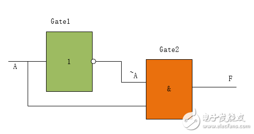
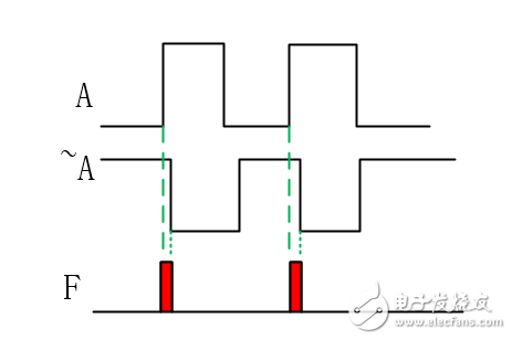
In fact, if the non-gate delay is counted, then F will eventually have a glitch. Because the signal transmission through different paths reaches a certain confluence point, there is a phenomenon of succession, which is called competition. The phenomenon of instantaneous error in the circuit output caused by competition is called adventure. We should pay attention to avoid this phenomenon. The simplest way to avoid this is to use sequential logic to synchronize output as much as possible.
This adventure between state machine and combinatorial logic is here. Next time we will talk about the adventure competition of sequential logic.
Panasonic Insertion Machine Parts
The Insertion machine can be divided into: a cross-line Insertion machine, an axial component Insertion machine, and a radial component Insertion machine.
Panasonic Insertion Machine Parts include Cutter, Ball Screw, WH Flex Cable, Photo Interrupt, Clinch Lever, Belt, Pallete,Shaft Assy,Guide,Scissors Unit etc.
Panasonic Insertion Machine Parts,Insertion Machine Fiber Sensor,Insertion Machine Solenoid Valve,Insertion Machine Solenoid Valve
Shenzhen Keith Electronic Equipment Co., Ltd. , https://www.aismtks.com