With the continuous development of mechanization, electrification and automation in the production process, various types of special motors have emerged. The working principles of these motors are generally similar to the basic principles of ordinary asynchronous motors and DC motors, but they have their own characteristics in performance, structure, and production technology, and are mostly used in automatic control processes. In general, the power of these motors is not large, the small is only a fraction of a watt, and the large is only a few tens or hundreds of watts, which belongs to the scope of micro motors.
Stepping motor
Generally, the motor rotates continuously, but the stepper motor rotates step by step, so it is called a stepper motor. Each time an impulse signal is input, the motor rotates through a certain angle (some stepper motors can directly output linear displacement, called linear motors). Therefore, the stepper motor is an actuator that changes the pulse into angular displacement (or linear displacement).
The rotor of the stepping motor is multi-pole distributed. The stator is embedded with multi-phase star-connected control windings. The electrical pulse signal is input by a special power supply. Each time a pulse signal is input, the rotor of the stepping motor advances. Because the input is a pulse signal, the angular displacement of the output is intermittent, so it is also called a pulse motor.
With the development of digital control systems, the application of stepper motors will gradually expand.
There are many types of stepping motors, which can be divided into two types: reactive and excitation according to the structure; according to the number of phases, they can be divided into three types: single-phase, two-phase and multi-phase.
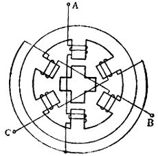
Figure 1 Schematic diagram of the reaction stepper motor
Figure 1 is a schematic diagram of the structure of a reactive stepping motor. Its stator has six magnetic poles evenly distributed, and windings are wound on the magnetic poles. Two opposing magnetic poles form a group, the joint method is shown in the figure. The basic principles of the reactive stepping motor single-three-beat, six-beat and double-three-beat energization methods are introduced below.
1. The basic principle of single-three-shot power-on method
Suppose that the phase A is energized first (the two phases B and C are not energized), generating magnetic flux in the AA ′ axis direction, and forming a closed loop through the rotor. At this time, the A and A 'poles become the N and S poles of the electromagnet. Under the action of the magnetic field, the rotor always tries to turn to the position with the smallest reluctance, that is, to the position where the teeth of the rotor align with the A and A ′ poles (Figure 2a); Powered on), turned it clockwise through 30 °, its teeth are aligned with the C and C ′ poles (Figure 2c). It is not difficult to understand that when the pulse signals are sent one by one, if the power is supplied in the order of A → C → B → A → ..., the motor rotor will rotate counterclockwise. This power-on method is called the single-three-shot method.
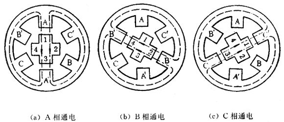
Figure 2 The basic principle of the rotor position in the single and three-beat energization method
Let Phase A be energized first, and the rotor teeth are aligned with stators A and A '(Figure 3a). Then turn on the B phase while the A phase continues to be energized. At this time, the stator B and B ′ poles generate magnetic pulling force on the rotor teeth 2, 4 to make the rotor rotate clockwise, but the A and A ′ poles continue to pull the teeth 1, 3, so the rotor turns to the balance of the two magnetic pulling forces . At this time, the position of the rotor is shown in Fig. 3b, that is, the rotor is rotated clockwise by 15 ° from the position of (a) in the figure. Then phase A is de-energized, and phase B continues to be energized. At this time, the rotor teeth 2 and 4 are aligned with the stator B and B ′ poles (figure c), and the rotor is rotated by 15 ° from the position in figure (b). Its location is shown in Figure 3d. In this way, if electricity is circulated in the order of A → A, B → B → B, C → C → C, A → A ..., the rotor will turn clockwise step by step with a step angle of 15 °. The current is switched six times, the magnetic field rotates once, and the rotor advances by a pitch angle. If power is supplied in the order of A → A, C → C → C, B → B → B, A → A ..., the motor rotor rotates counterclockwise. This power-on method is called the six-shot method.
Three, the basic principle of double three beats
If the two phases are energized every time, that is, energized in the order of A, B → B, C → C, A → A, B → ..., it is called double triple beat mode, as shown in Figure 3b and Figure 3d The pitch angle is also 30 °. Therefore, in the single three-beat and double three-beat modes, the rotor advances one pitch angle in three steps, and each step advances one-third of the pitch angle; in the six-beat mode, the rotor advances one tooth in six steps. The pitch angle advances by one-sixth pitch angle with each step. Therefore, the step angle θ can be calculated by the following formula:
θ ï¼ 360 ° / (Zr × m)
Where Zr is the number of rotor teeth; m is the number of running beats.
The most common step angle of a general stepping motor is 3 ° or 1.5 °. It can be seen from the above formula that there are not only 4 teeth (pitch angle 90 °) but 40 teeth (pitch angle 9 °) on the rotor. In order to align the rotor teeth with the stator teeth, the tooth width and pitch must be equal. Therefore, in addition to the 6 poles on the stator, there are 5 small teeth on each pole surface that are the same as the rotor teeth. The structure diagram of the stepping motor is shown in Figure 4.
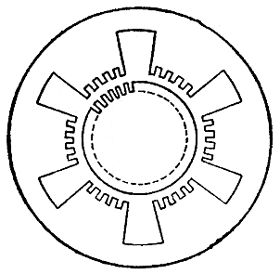
Figure 4 Structure diagram of the three-phase reaction stepper motor From the above introduction, it can be seen that the stepper motor has the characteristics of simple structure, convenient maintenance, high accuracy, sensitive start and accurate parking. In addition, the rotation speed of the stepper motor is determined by the frequency of the electric pulse and is synchronized with the frequency.
Fourth, the driving power of the stepping motor
The stepping motor needs to be equipped with a special power supply. The function of the power supply is to energize the control winding of the motor in a specific order, that is, it is controlled by the input electric pulse to operate. This special power supply is called the driving power supply. The stepping motor and its driving power supply are an interconnected whole. The running performance of the stepping motor is a comprehensive effect formed by the cooperation of the motor and the driving power supply.
1. Basic requirements for drive power
(1) The phase number, power-on mode, voltage, and current of the driving power supply all meet the needs of stepping motors;
(2) To meet the requirements of starting frequency and running frequency of stepping motor;
(3) It can suppress the oscillation of the stepping motor to the maximum extent;
(4) Reliable work and strong anti-interference ability;
(5) Low cost, high efficiency, convenient installation and maintenance.
Printed ESD Shielding Membrane Switch
An antistatic Membrane Switch, including from down to up in turn to paste the bottom of the rubber, the line, the line key layer, electrostatic layer, surface key layer, panels, the line is equipped with switch button on the layer, on the panel layer is equipped with a transparent window, at the bottom of the transparent window in front of the key lines, static layer, layer key layer, the line, open a corresponding hole in the bottom rubber, Described panel layer surface corresponding to the mentioned switch button position with boss, as described in surface layer and described line keys described layer corresponds to the location of the switch button piece with a hole, whose character is: the surface described key layer hole with transparent conductive film, end lead to membrane switch and grounding, electrostatic layer of transparent conductive and transparent window and electrostatic layer conductive paste.
Printed Esd Shielding Membrane Switch,Electronic Infusion Pump Membrane Switch,Electronic Membrane Switch,Silver Pet Membrane Switch
Dongguan Nanhuang Industry Co., Ltd , https://www.soushine-nanhuang.com