1 Introduction
This article refers to the address: http://
The H.264 video compression standard is highly adaptable to wireless multimedia and Internet-based applications due to its high compression efficiency and good network support. In the process of information transmission, the inevitable is noise. H.264 itself has good anti-noise technology, such as SPS, PPS and image data are packaged separately. There can be multiple slices in one frame, flexible macroblock order (FMO) and so on. But there are also many cases where the error cannot be completely fixed. H.264 has a very high compression ratio (7 to 50 times), which means that the redundancy in the image has been greatly eliminated, and it is very difficult to recover images from the rest of the code stream. In addition, the H.264 compression standard uses variable length coding CAVLC and CABAC. Once an error occurs in these places, the decoder will not be able to judge the position of the next variable length code, resulting in the spread of errors.
In terms of hardware, the implementation of each part of the decoding process has its fixed structure. If the error is not detected in time, it will lead to memory overflow, table lookup error, state machine entering an infinite loop. The decoded image will be misplaced or distorted. In the worst case, the entire decoder will stop running.
Therefore, it is very meaningful and necessary to add error correction function to the decoder to find the code stream noise early and restore the decoder to the normal state.
The decoder for this project is an SoC-based ASIC solution with high speed, low power consumption and low cost. Adding error correction function can improve the applicability and stability of the decoder. On the other hand, the influence of the error correction module on the area and speed of the original chip should be minimized.
2 code stream structure and error detection
The H.264 standard compressed code stream has a strict format. The public information is extracted as SPS (Sequence Parameter Set), and the PPS (Image Parameter Set) is separately packaged and separated from the pixel information. SPS and PPS are extremely important information in the code stream. Packing them separately can transmit multiple times in the case of poor transmission environment, which enhances the anti-interference ability of code stream transmission to a certain extent. Each packet is called a NAL unit, and according to the NAL type, the data in each packet is closely arranged in the order of the syntax elements specified in the protocol. This provides two conveniences for error correction: (1) errors in each NAL do not spread, that is, if an error is detected in the current NAL and it is not possible to determine where the error terminated, the current packet can be discarded until the next NAL begins; (2) many syntax elements have their fixed scope. It is a very useful way to detect if the decoded element value is out of range. It can also find errors as early as possible to prevent the decoder from entering an abnormal state.
The H.264 video stream consists of five levels of information: sequence layer, image layer, slice layer, macroblock layer, sub-macroblock layer, respectively, with NAL type SPS, PPS, Slice (including slice header, macroblock, sub-macro) Block information) corresponds.
Macroblocks are the basic unit of codec processing and the basic unit for error repair. The H.264 video code stream structure is shown in Figure 1.
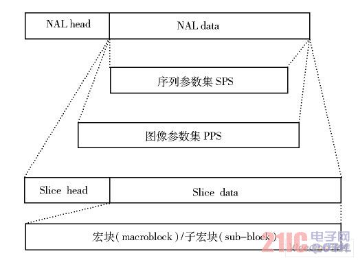
Figure 1 H.264 code stream structure
In the above several levels, each layer has its specific syntax element structure, and the corresponding syntax processing method, the entire error detection function is based on this implementation. The errors that can currently be detected are based on the following categories:
(1) Reserved bit error. This is the easiest error to detect. Some reserved bits are specified in the H.264 protocol, such as forbidden_zero_bit at the beginning of NAL, reserved_zero_4bits in SPS, and so on. When the decoder reads the code stream sequentially, it is necessary to determine that the values ​​of these reserved bits are correct. If there is an error, the current packet or flag error should be discarded for further processing.
(2) The syntax element value is not in the specified range. Most syntactic elements, especially in SPS and PPS, have a specified range. For example, log2_max_frame_num_minus4 used to calculate the maximum number of frames must be between 0 and 12. If the value read in is out of this range, it can be judged that there is an error in the currently read code stream.
(3) Contradictions in related syntactic elements. Some syntax elements read in an incorrect value, but are still in the correct range and cannot be detected by the current statement alone. At this time, it is necessary to use the correlation between syntactic elements to judge whether the value read is reasonable. For example, in the PPS, you need to specify the sequence parameter information referenced by the current image, that is, PPS->seq_parAMEter_set_id. If the ID of the currently referenced SPS does not exist in all received SPSs, it can be judged that there is a problem with one of the SPS or the current PPS; for the various types of I, B, and P of slice_type, the lookup method of mb_type is different. If the macroblock type of inter prediction occurs in the I slice, an error can also be judged.
The above methods can be judged by the value of the syntax element itself, and can be processed while reading the code stream, that is, adding the judgment after processing the corresponding statements of PPS and SPS, which will not affect the original decoder too much. .
Not all code stream errors can be directly judged by the value of the syntax element. The values ​​of some syntax elements affect the decoding method and are reused, so some errors can be found during the decoding process, for example:
(4) The reference cited does not exist. One of the ways in which H.264 implements compression is to use intra and inter prediction, such as four 16×16 intra prediction modes and nine 4×4 intra prediction modes. The various modes have different requirements for the surrounding macroblocks, and the adjacent macroblock information required for the horizontal intra prediction mode of the 16×16 block is as shown in FIG. 2 . If the current macroblock X uses horizontal intra prediction, then macroblock A must be available. If the current macroblock is on the first of the lines, then this prediction is wrong. In the inter-frame prediction, the number and position of the reference image where the reference block is located are specified. If the position of the reference frame or the reference block pointed to by the current number does not exceed the image range, the current reference is incorrect. Since macroblock information uses variable length coding and no specific symbol partitioning, once an error is found, subsequent data should be discarded until the beginning of the next NAL.
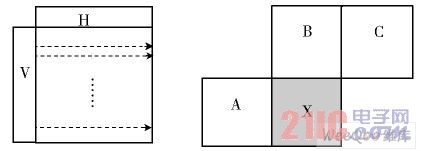
Figure 2 Brightness component Intra 16×16 horizontal prediction mode
(5) There is no corresponding value in the lookup table. CAVLC and CABAC-encoded data are difficult to separate out-of-error data because of their code length, but decoding these data contains a large number of look-up tables, which is very helpful for early detection of errors.
(6) Other abnormal conditions. If there is a vacancy in the reference queue, at this time, it can only be judged that a memory management error has occurred in the previous frame or frames, the management enable syntax element daptive_ref_pic_marking_mode_flag is incorrectly set, or the specific operation type is incorrect. In this case, the error cannot be determined immediately when the syntax element is decoded (the value is in the normal range and the queue does not have an exception), although it can be checked according to the situation of inserting the reference frame into the queue after manual debugging, but for real time. This is meaningless for the decoder. At this time, it is not necessary to abandon the data in the current NAL, as long as the information of the adjacent reference frame is copied into the reference queue.
The above is a rough outline of the error detection method. Since the noise is random, the error may occur anywhere in the decoding process, so only by debugging a large number of code streams can a certain error coverage be achieved, so that the decoder has better adaptability.
3 Error Correction Implementation in Software and Hardware Cooperative System
Although a more complete error patching method is given in H.264's official reference software JM, considering the minimization of the impact of the error correction part on the original hardware, we use a patching method based on intraframe 16×16 prediction. The principle is similar to the method of decoding intra 16×16 predictions. If an error occurs from a certain macroblock, the decoder will judge the existence and prediction of the surrounding macroblock, select an optimal prediction mode for the current macroblock, and repair the current macroblock by the pixel value on the boundary of the peripheral macroblock. Subsequent macroblocks until the current slice ends.
The decoder adopts a SoC implementation scheme of software and hardware coordination. In terms of function partitioning, the work of SPS / PPS / Slice header parsing and other branches is more implemented by the software part with higher flexibility. The work of entropy decoding and macroblock prediction, which requires a lot of complex operations, is implemented by hardware modules. The hardware part is divided into two parts: the front end and the back end. The front part includes an entropy decoding unit, IQ / IDCT, and the back end includes motion compensation (MC) and filtering module.
The CPU communicates with each module and module using the wishbONe bus. There is another data channel between the front and rear processing units to share the overhead of the wishbone bus. The structure is shown in Figure 3. The CPU performs preliminary processing on the input code stream, extracts information such as image size and frame type, and then sends the processed data to the front end processing part of the hardware, and the output of the front end processing is sent to the motion compensation module to recover the pixel information and Remove blockiness.
Error detection is done by both hardware and software. The software [5] judges whether the values ​​of the solved syntax elements are reasonable while parsing the SPS, PPS, and Slice head. If there is an error, the signal HasErr_soft is sent to the hardware through the bus. For example, in the function that parses the PPS, the decoded unsigned exponent Columbus (ue) is used to represent the syntax element seq_parameter_set_id of the SPS ID called by the current PPS, and then determines whether the decoder has received the SPS of this ID label. If there is no such SPS , interrupts the decoding of the current PPS and returns to the previous function. The parameters of the current PPS are copied from other PPS. That is to make the following modifications in the software section:
Read_new_slice() / / read in a NAL unit
{
...
Switch (nalu->nal_unit_type) / / determine the NAL type
{
...
Case NALU_TYPE_PPS:
ProcessPPS(nalu); / / PPS analysis
Break;
...
}
}
ProcessPPS(NALU_t 觹nalu)
{
...
Pps->seq_parameter_set_id =ue_v(...);
/ / Read the SPS_id corresponding to the current PPS
If (pps->seq_parameter_set_id invalid)
/ / If the read SPS_id is not available
... / / Copy the contents of the previous PPS
HasErr=1; / / error flag position 1
/ / (will send signals to the hardware via the bus)
Return;
}
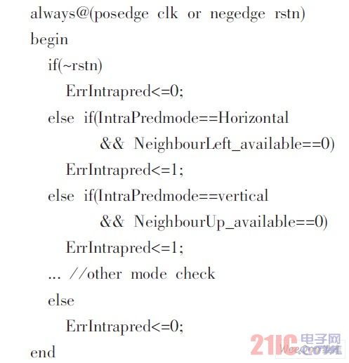
The hardware is mainly responsible for decoding the macroblock layer and the sub-macroblock layer, and can find errors in prediction mode and entropy decoding. If an error is detected during hardware decoding, the hardware sends a HasErr_hw signal to the software. For example, in intra prediction, it is necessary to judge the availability of adjacent macroblocks. Add the following judgment after reading the statement of the intra prediction mode:
The entire error correction process is controlled by software, and the patching process sends data directly to the hardware back end. The hardware detects the error and passes the HasErr signal to the software. The software performs the corresponding data processing, sends the Err_Processing signal to the hardware, and provides data to the decoder backend according to the error patching scheme instead of the front-end data processing part, as shown by the dotted line in Figure 3. .
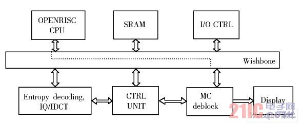
Figure 3 H.264 decoder structure
In the patching process, the intra prediction portion of the original hardware can be used because of the prediction based on spatial continuity. However, some of the original signals need to be processed accordingly after the error, otherwise some state opportunities of the control part enter the abnormal state and the hardware cannot continue to operate normally.
4 Experimental results
This experiment first modified and improved the C model on the PC, and the hardware test platform used the Xilinx Virtex4 series development board. The decoder software part is written in C language, compiled under gcc under Linux, and the generated binary file runs on an open core OPENRISC1200-based CPU; the hardware part is described using Verilog HDL. The input stream used for the test is a reference sequence [2] provided by ITU-T, adding 11 fixed noise samples. The experiment proves that the proportion of the noise code stream that the decoder can decode smoothly is greatly improved, the image playback is smooth, and many damaged places are better repaired, but some can also see obvious repair traces.
5 Conclusion
Adding error checking and patching to the decoder improves the decoder's ability to handle corrupted streams, allowing the decoder to be used in more complex environments with increased stability. The H.264 video compression standard itself has some techniques that support error patching, such as multiple transmissions of SPS and PPS, multiple slices, FMO, and so on. Multiple transmissions of SPS and PPS at the expense of reduced transmission efficiency result in higher accuracy at the receiving end, which is necessary in some environments. Multiple Slices and FMOs increase the complexity of encoding and decoding to a certain extent, but it allows more peripheral macroblock information to be used for prediction and patching of corrupted macroblocks. In addition, as far as the patching method is concerned, there are also studies based on inter-frame correlation and other intra prediction interpolation methods. The main goal of this experiment is to enable the decoder to decode smoothly and reuse existing hardware units as much as possible, reducing the increase in hardware area due to the addition of error correction. Repaired by 16×16 intra prediction, the image quality is greatly improved compared to the unpatched, but there are still some obvious repair marks in some places. Look for a better image patching method, so that the patched image is as close as possible to the original image, reducing the traces of repair that can be clearly distinguished. These are the things that need to be studied.
Home Using Solar Charger Controller use high-end shell which make of ABS engineering plastics. It has high strengh impact resistance. Heat-sink bottom desighned in line with aerodynamics is made of aviation aluminium materials. The wide cross-sectional are design connector makes connection easier.With our strict quality control, our home using Solar Charger Controller helps you build a sweet home.
Home Using Solar Charger Controller
Inverter Charger,Home Using Solar Charger Controller,Home Solar System Mppt Controller,Home Solar Systems Charge Controller
Guangzhou City Poojin Electronic Technology Co., Ltd. , http://www.inverter-belttt.com