In practical industrial, power, automation, and instrumentation applications, the RS-485 bus standard is one of the most widely used physical layer bus design standards, as it operates in harsh electromagnetic environments, to ensure that these data ports are ultimately They work properly in the installation environment and they must comply with the relevant electromagnetic compatibility (EMC) regulations. In this paper, Shijian Company combines the advantages of the agent line ADI (RS-485 chip), Bourns (in the port EMC protection device), from the principle analysis to the actual measurement to bring you detailed RS485 port protection analysis.
In the EMC design of the RS-485 port, we need to consider three factors: electrostatic discharge (ESD), electrical fast transient (EFT), and surge (Surge). The International Electrotechnical Commission (IEC) specification defines a set of EMC immunity requirements that include the following three types of high voltage transients, and designers need to ensure that data communication lines are not compromised by these transients. These three types are:
· IEC 61000-4-2 Electrostatic Discharge (ESD)
· IEC 61000-4-4 Electrical Fast Transient (EFT)
· IEC 61000-4-5 Surge Immunity (Surge)
Angus Zhao, deputy director of technical support at Excelpoint, said: "The protection scheme for RS-485 ports is to meet the requirements of ESD, EFT and Surge. So you want to design a compliant RS-485 port. For the EMC solution, we must first thoroughly understand the three specifications. "The domestic equivalent standards for IEC standards can also be referenced. For example, in power and transmission and distribution applications, many adopt GB/T17626.2 ESD, GB/T17626. 4 EFT, GB/T17626.5 Surge corresponding standard specification, this article uses the IEC standard as an example.
Electrostatic dischargeElectrostatic discharge (ESD) refers to the sudden generation of electrostatic charge transfer between two charged bodies with different potentials due to the conduction of near contacts or electric fields. Its characteristic is that it has a large current in a short time. The main purpose of the IEC 61000-4-2 test is to determine the immunity of the system to external ESD events during operation. IEC 61000-4-2 specifies voltage test levels for different environmental conditions and is divided into four levels. Level 1 is the slightest and level 4 is the most serious. Levels 1 and 2 are suitable for products installed in a controlled environment with antistatic materials. Levels 3 and 4 are suitable for products installed in more severe environments where ESD events with higher voltages are more common.
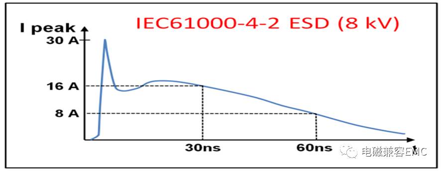
Figure 1: ESD characteristic curve. 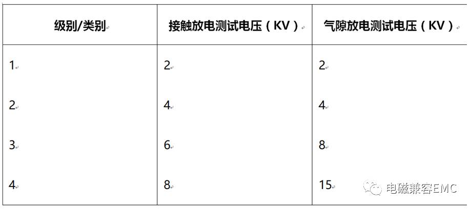
Figure 2: IEC 61000-4-2 ESD test level and installation category.
Electrical Fast Transient (EFT) tests a large number of extremely fast transient pulses coupled to the signal line, transient disturbances associated with external switching circuits that can be capacitively coupled to the communication port. EFT wraps include relay and switch contact jitter, or transients due to inductive or capacitive load switching, all of which are common in industrial environments. The EFT test defined in EC 61000-4-4 is to simulate the interference generated by these events.
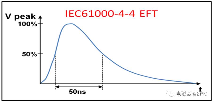
Figure 3: EFT characteristic curve.
IEC 61000-4-4 specifies voltage test levels for different environmental conditions and is divided into four levels. Test voltages and pulse repetition rates corresponding to different test levels are also specified.
· Level 1 indicates a good environment for protection
· Level 2 indicates a protected environment
· Level 3 indicates a typical industrial environment
· Level 4 indicates poor industrial environment
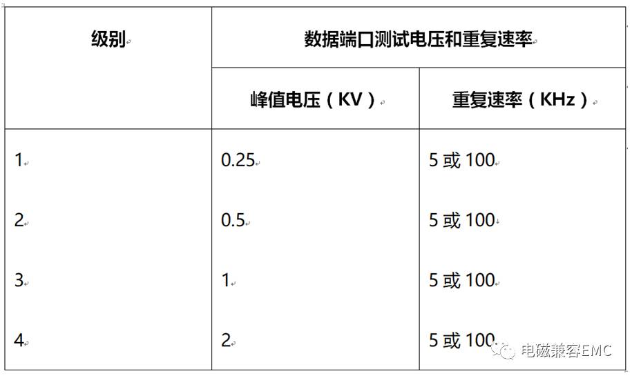
Figure 4: IEC 61000-4-4 EFT test level.
SurgeSurge is usually caused by overvoltage conditions or lightning strikes caused by switching operations. Switching transients can be caused by power system switching, load changes in the power distribution system, or various system faults. The cause of a lightning strike transient may be that a nearby lightning strike causes a large current and voltage to be injected into the circuit. IEC 61000-4-5 defines waveforms, test methods and test levels for assessing the immunity of electrical and electronic equipment subject to the effects of these surges.
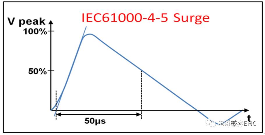
Figure 5: Surge characteristic curve.
The energy level of the surge can reach three to four orders of magnitude of the ESD or EFT pulse energy level. Therefore, surges can be considered the most serious of the EMC transient specifications. Due to the similarity between ESD and EFT, the corresponding circuit protection design is similar, but due to the high energy of the surge, different treatments must be taken.
Angus Zhao, deputy director of the technical support department of Excelpoint, said: "The process of developing EMC protection circuits is to meet the specifications of the above three transient immunity according to the actual application scenario, while ensuring the cost. Benefits. This seemingly complicated work actually has its own principles and routines to follow."
The corresponding specification requirements for the RS-485 port EMC solution are actually the goals that the protection circuit design needs to achieve. In order to achieve such a goal, it has its own design principles:
There are two main ways to protect against transients: overcurrent protection is used to limit peak current; overvoltage protection is used to limit peak voltage. Typical protection scheme designs include primary and secondary protection. Master protection removes most of the transient energy from the system, usually between the system and the environment, and it transfers transients to the ground, removing most of the energy. The purpose of the secondary protection is to protect the various components of the system from any transient voltages and currents that the primary protection is allowed to pass. Secondary protection is usually more focused on specific components facing the protected system. It is optimized to ensure protection against these residual transients while allowing these sensitive components of the system to function properly. Angus Zhao, deputy director of Excelpoint's technical support department, said: "These two methods must ensure that the primary and secondary designs work together with the system inputs/outputs to minimize stress on the protected circuit. There is typically a coordination element between the primary protection device and the secondary protection device, such as a resistor or a non-linear overcurrent protection device to ensure coordination."
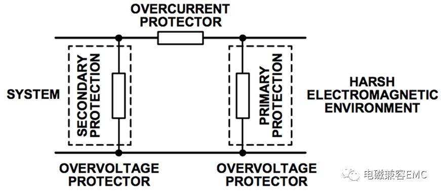
Figure 6: Traditional EMC protection solution architecture.
In accordance with the above specification requirements and design principles, we provide three different levels of EMC protection solutions, all of which have been certified by third-party independent EMC compatibility testing. The components used in the solution include:
· ADM3485EARZ 3.3 V RS-485 Transceiver (ADI)
· TVS Transient Voltage Suppressor CDSOT23-SM712 (Bourns)
· TBU transient blocking unit TBU-CA065-200-WH (Bourns)
· TIST Thyristor Surge Protector TISP4240M3BJR-S (Bourns)
· GDT gas discharge tube 2038-15-SM-RPLF (Bourns)
Option OneThe energy levels of EFT and ESD transients are similar, and the energy level of a surge waveform is three to four orders of magnitude higher. Protection against ESD and EFT can be done in a similar manner, and protection solutions for high-level surges are more complex. The first solution provides four levels of ESD and EFT and two levels of surge protection.
This solution uses Bourns' CDSOT23-SM712 TVS array, which includes two bidirectional TVS diodes. TVS is a silicon based device. Under normal operating conditions, TVS has a high impedance to ground; ideally it is open circuited. The protection method is to clamp the overvoltage caused by the transient to the voltage limit. This is achieved by low impedance avalanche breakdown of the PN junction. When a transient voltage greater than the breakdown voltage of the TVS is generated, the TVS clamps the transient to a predetermined level less than the breakdown voltage of the protection device, and less than 1 ns, the transient current can be transferred from the protected device to the ground. .
It is important to ensure that the breakdown voltage of the TVS is outside the normal operating range of the protected pin. The unique feature of the CDSOT23-SM712 is an asymmetric breakdown voltage of +13.3 V and –7.5 V, which matches the common-mode range of the +12 V to –7 V transceiver of the RS-485 chip ADM3485E to provide the best Protection while minimizing overvoltage stress on the RS-485 transceiver.
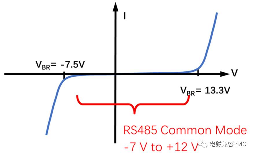
Figure 7: CDSOT23-SM712 TVS characteristic curve.
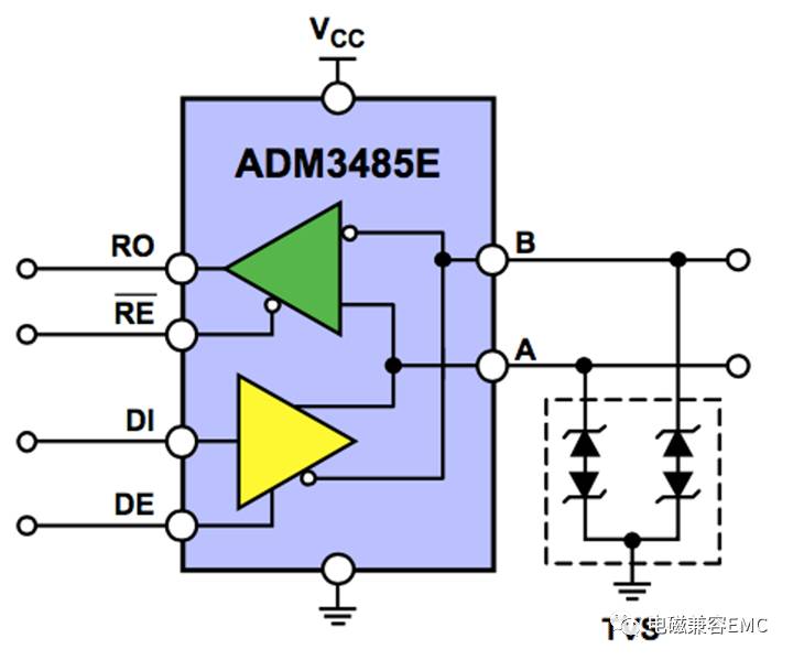
Figure 8: Protection scheme based on TVS array.
Option IIIf we want to improve the level of surge protection, the protection circuit will become more complicated. In Option 2, we will increase the surge protection to level 4.
In this scheme, secondary protection is provided by TVS (CDSOT23-SM712), and main protection is provided by TISP (TISP4240M3BJR-S). Coordination between the primary protection device and the secondary protection device and overcurrent protection are utilized by Bourns patented technology. Overcurrent protection device TBU (TBU-CA065-200-WH).
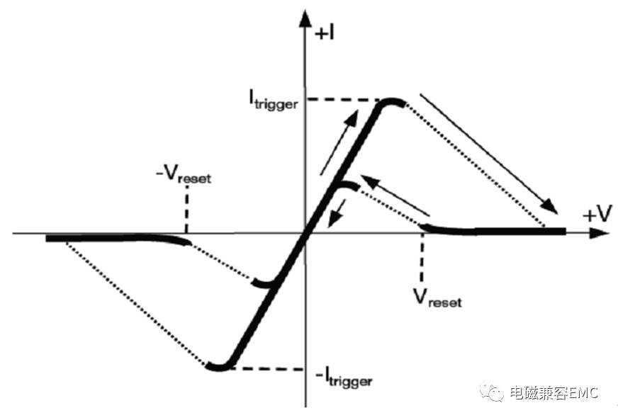
Figure 9: Characteristic curve of the TBU.
When transient energy is applied to the protection circuit, the TVS will break down, protecting the device by providing a low impedance ground path. Due to the high voltage and current, the TVS must also be protected by limiting the current through it. This can be done with a TBU, an active high-speed overcurrent protection element that blocks current rather than shunting it to ground. As a series component, it reacts to the current through the device, rather than reacting to the voltage across the interface. The TBU is a high speed overcurrent protection component with preset current limits and high voltage immunity. When an overcurrent occurs and the TVS breaks down due to a transient event, the current in the TBU will rise to the current limit set by the device. At this point, the TBU will disconnect the protected circuit from the surge for less than 1 μs. During the remainder of the transient, the TBU remains protected and the current through the protected circuit is very small (less than 1 mA). Under normal operating conditions, the TBU has low impedance, so it has little effect on normal circuit operation. In blocking mode, it has a high impedance to block transient energy. After a transient event, the TBU automatically resets to a low impedance state, allowing the system to resume normal operation.
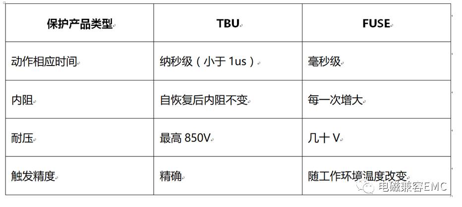
Figure 10: Difference between TBU and PTC (Fuse).
As with all overcurrent protection techniques, the TBU has the maximum breakdown voltage, so the primary protection device must clamp the voltage and redirect the transient energy to ground. This is typically accomplished using techniques such as gas discharge tubes or solid discharge tubes (thyristors) TISP, such as TISP. TISP acts as a primary protection device that provides a transient open low-impedance ground path when it exceeds its predefined protection voltage, thereby transferring most of the transient energy away from the system and other protection devices.
The nonlinear voltage-current characteristics of TISP limit the overvoltage by diverting the current generated. As a thyristor, TISP has a discontinuous voltage-current characteristic which is caused by a switching action between a high voltage region and a low voltage region. Before the TISP device switches to a low voltage state, it has a low impedance ground path to shunt transient energy, and an avalanche breakdown region results in a clamping action.
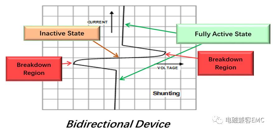
Figure 11: Characteristic curve of TISP.
During the regulation of overvoltage, the protected circuit is briefly exposed to high voltage, so the TISP device is in the breakdown region before switching to the low voltage protection open state. The TBU will protect the back-end circuitry from damage caused by high currents caused by such high voltages. When the transfer current drops below the critical value, the TISP device automatically resets to resume normal system operation.
All three of these components work together to work with the system inputs/outputs to provide system level protection for high voltage, high current transients.
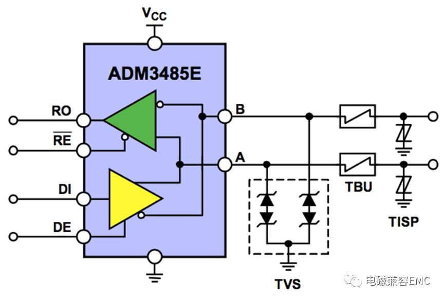
Figure 12: TVS, TBU, and TISP work together to provide a higher level of protection.
third solutionIf the protection scheme needs to cope with surge transients of up to 6 kV, then some adjustments need to be made to the solution. The new scheme works in a similar way to protection scheme 2; however, this circuit uses a gas discharge tube (GDT) instead of TISP to protect the TBU, thereby protecting the secondary protection device TVS. Compared to TISP, GDT uses the gas discharge principle to provide protection against greater overvoltage and overcurrent stresses. The rated current of TISP is 220 A, and the rated current of GDT is 5 kA (calculated as unit conductor).
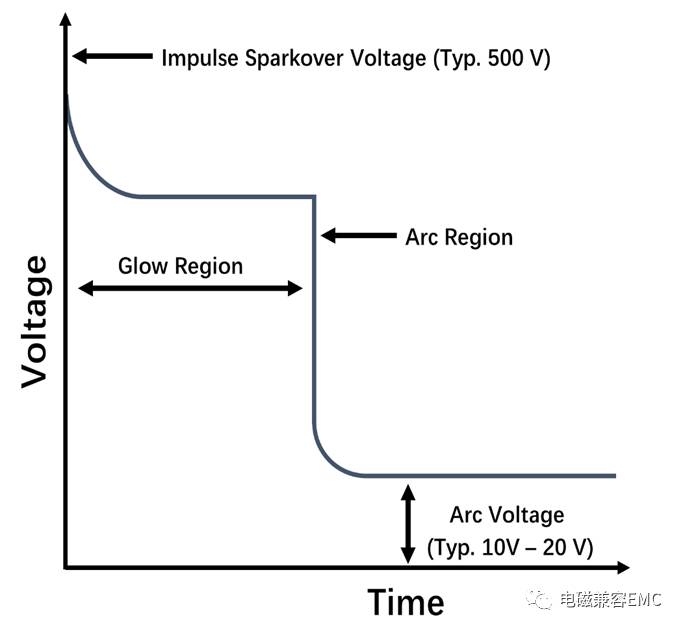
Figure 13: Characteristic curve of the GDT.
The GDT is primarily used as a primary protection device to provide a low impedance ground path to prevent overvoltage transients. When the transient voltage reaches the GDT spark discharge voltage, the GDT will switch from the high impedance off state to the arc mode. In arc mode, the GDT becomes a virtual short circuit that provides a transient open current grounded bleed path that diverts transient inrush current from the protected device.
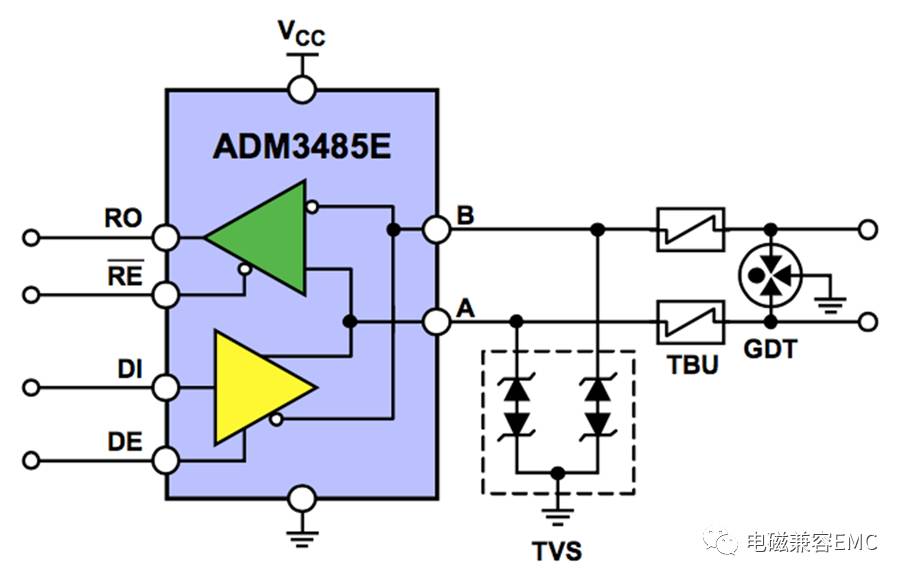
Figure 14: Working with TVS, TBU, and GDT can withstand greater overvoltage and overcurrent stresses.
Angus Zhao, deputy director of the technical support department of Excelpoint, concluded that the EMC solution of the RS-485 port has its own routine, understands the specifications that the protection needs to follow, and is familiar with the characteristics of the circuit protection device. It is not difficult to make a compliance design.

Figure 15: Comparison of EMC scheme protection levels for three RS485 ports.
Finally, Shijian also introduced two classic and practical RS-485 port protection schemes, which can pass the IEC6100-4-2 ESD, IEC61000-4-4 EFT, IEC61000-4-5 Surge Level 4 EMS safety test.
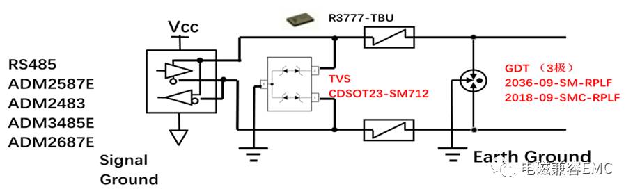
Figure 16: Scheme 1, using a 3-pole GDT+TBU+TVS architecture.
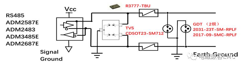
Figure 17: Option 2, using a 2-pole GDT+TBU+TVS architecture.
Aluminum Cell Phone Stand, Durable Cellphone,Desk Cell Phone Stand Holder Aluminum Phone Dock Cradle,etc.
Shenzhen Chengrong Technology Co.ltd is a high-quality enterprise specializing in metal stamping and CNC production for 12 years. The company mainly aims at the R&D, production and sales of Notebook Laptop Stands and Mobile Phone Stands. From the mold design and processing to machining and product surface oxidation, spraying treatment etc ,integration can fully meet the various processing needs of customers. Have a complete and scientific quality management system, strength and product quality are recognized and trusted by the industry, to meet changing economic and social needs .

Aluminum Vell Phone Stand,Aluminum Cell Phone Desk Stand,Cell Phone Holder For Stand,Cell Phone Stands
Shenzhen ChengRong Technology Co.,Ltd. , https://www.dglaptopstandsupplier.com