A stepper motor is an actuator that converts electrical pulses into angular displacement. When the stepper driver receives a pulse signal, it drives the stepper motor to rotate in a set direction by a fixed angle (called "step angle"), and its rotation runs at a fixed angle. The angular displacement can be controlled by the number of control pulses to achieve accurate positioning. At the same time, the speed and acceleration of the motor can be controlled by controlling the pulse frequency to achieve the purpose of speed regulation. As a special motor for control, stepper motor is widely used in various open-loop control because it has no accumulated error (100% accuracy).
Positioning principle and scheme
Stepper motor acceleration and deceleration control principle
When the stepper motor drives the actuator from one position to another, it undergoes a speed up, constant speed and deceleration process. When the running frequency of the stepping motor is lower than its own starting frequency, it can be started directly with the running frequency and run at this frequency. When it needs to stop, it can be directly reduced from the operating frequency to zero speed. 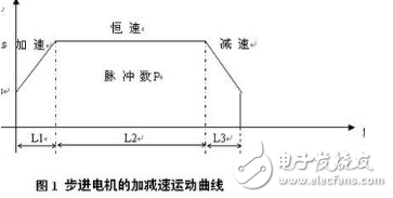
When the stepping motor running frequency fb>fa (starting frequency when starting the load), if the frequency is started directly with the fb frequency, the stepping motor will be out of step or even blocked. Also, when suddenly stopping at the fb frequency, the stepping motor will overshoot due to the inertia, which affects the positioning accuracy. If the speed is very slow, the stepper motor will not cause out-of-step and overshoot, but it will affect the efficiency of the actuator.
Therefore, the stepping motor acceleration and deceleration must be guaranteed to move to the specified position with the fastest speed (or the shortest time) without losing the step and overshoot.
There are two kinds of lifting frequency control methods commonly used in stepping motors: linear lifting frequency and exponential curve lifting frequency. The exponential curve method has strong tracking ability, but the balance is poor when the speed changes greatly. The straight line method has good smoothness and is suitable for fast positioning methods with large speed changes. With a constant acceleration and lowering, the law is concise, and it is relatively simple to implement with software. This method is adopted in this paper.
Positioning plan
To ensure the positioning accuracy of the system, the pulse equivalent, that is, the distance that the stepping motor moves by one step angle can not be too large, and the stepping motor's lifting speed should be slow to prevent out-of-step or overshoot. But these two factors together bring up a prominent problem: the positioning time is too long, affecting the efficiency of the actuator.
Therefore, in order to obtain a high positioning speed and at the same time to ensure the positioning accuracy, the entire positioning process can be divided into two stages: a coarse positioning stage and a fine positioning stage.
In the coarse positioning stage, a larger pulse equivalent is used, such as 0.1 mm/step or 1 mm/step, or even higher.
In the fine positioning stage, in order to ensure the positioning accuracy, a smaller pulse equivalent is used, such as 0.01 mm/step. Although the pulse equivalent becomes small, since the fine positioning stroke is short (can be set to about one-fifth of the full stroke), the positioning speed is not affected. To achieve this, the mechanical aspects can be achieved by using different shifting mechanisms.
Industrial machine tool control plays an important role in industrial automation control, and positioning drilling is a common step. Set the tool or workbench to move from point A to point C, known as AC=200mm, divide AC into two sections AB and BC, AB=196mm, BC=4mm, AB section is coarse positioning stroke, adopt 0.1mm/step The pulse equivalent is rapidly moved according to the linear lifting frequency law, and the BC segment is a fine positioning stroke. The pulse equivalent of 0.01 mm/step is used to accurately position the low-frequency constant velocity movement at point B. At the same time as the coarse positioning ends and the fine positioning is completed, the PLC automatically realizes the replacement of the shifting mechanism.
Overview of the positioning program design content
PLC pulse output command
At present, more advanced PLCs not only have basic logic instructions that meet the requirements of sequential control, but also provide a wealth of functional instructions. The PLUS command of the Siemens S7-200 series PLC outputs PTO or PWM high-speed pulses at Q0.0 and Q0.1 with a maximum output frequency of 20KHz. The pulse train (PTO) provides a square wave output (50% duty cycle), user control period and number of pulses. Pulse Width Modulated (PWM) ketones provide continuous, variable duty cycle output, user control period and pulse width.
In this paper, the multi-stage pipeline working mode of PTO is used to realize coarse positioning, and the single-stage pipeline mode of PTO realizes fine positioning.
In the above example, it is assumed that the starting and ending frequencies of the motor are 2 kHz and the maximum pulse frequency is 10 kHz. In the coarse positioning process, the up-conversion acceleration is completed with 200 pulses, and the down-conversion is completed with 400 pulses. When using the PTO multi-segment pipeline pulse output of the PLC, use the following formula to calculate the pulse increment value during the ramp-up process.
Cycle increment for a given segment = (ECT - ICT) / Q
Where: ECT = the end cycle time of the segment, ICT = the initial cycle time of the segment. Using this formula, the acceleration portion (1st segment) has a period increment of 2, and the deceleration portion (3rd segment) has a period increment of 1. Since the second segment is the constant velocity portion, the cycle increment is zero. If the PTO envelope table is stored from VB500, Table 1 is the envelope table value of the above example.
Source program
Main program LD SM0.1 //The first scan is 1R Q0.0, 1 //Reset image register bit CALL 0 //Invoke subroutine 0, initialize coarse positioning related parameter LD M0.0 //Rough positioning complete R Q0.0 , 1CALL 1 / / call subroutine 1, initialization fine positioning related parameters / / subroutine 0, coarse positioning LD SM0.0
MOVB 16#A0,SMB67 //Set control word: Allow PTO operation, select ms increment, select multi-stage operation MOVW 500, SMW168 //Specify the starting address of the envelope table as V500MOVB 3, VB500 //Set the envelope table The number of segments is 3MOVW 500, VW501 //Set the initial period of the first segment to 500msMOVW -2, VD503 //Set the increment of the first segment to -2msMOVD 200, VD505 //Set the number of pulses in the first segment to 200MOVW 100 , VW509 / / set the second period of the initial period is 100msMOVW 0, VD511 / / set the second period increment is 0msMOVD 1360, VD513 / / set the second segment of the number of pulses is 1360MOVW 100, VW517 / / set The initial period of the third segment is 100msMOVW 1, VD519 //Set the third segment period increment to 1msMOVD 400, VD521 //Set the third segment pulse number to 400ATCH 2,19 //Define interrupt program 2 to process PTO completion interrupt ENI //Allow interrupt PLS 0 //Start PTO operation subroutine 1, fine positioning LD SM0.0 //First scan for 1MOVB 16#8D, SMB67 //Allow PTO function, select ms increment, set pulse number and period MOVW 500, SMW68 //Set the fine positioning period to 500msMOVD 400, SMD72 //Set the number of pulses to 400ATCH 3,19 //Definition Program 3 handles PTO completion interrupt ENI //Allows interrupt PLS 0 //Starts PTO operation//Interrupt program 2LD SM0.0 //Always 1= M0.0 //Start fine positioning//Interrupt program 3LD SM0.0 // Always 1 = M0.1 // implement other functions
24V Battery Pack ,Large Battery Pack,24 V Battery Pack,24V Lithium Ion Battery Pack
Zhejiang Casnovo Materials Co., Ltd. , https://www.casnovo-new-energy.com