When studying analog-electric power in college, I have been able to distinguish between two concepts. Sometimes I will confuse the two circuit diagram principles until I have done several modular electrical and electrical projects to truly understand the connection and difference.

Analog Circuit: An electronic circuit that processes analog signals. The word "analog" mainly refers to the reproduction of voltage (or current) proportional to the real signal. It originally originated from the Greek word ανάλογος, meaning “proportionalâ€.

A digital circuit is a circuit that performs arithmetic operations and logic operations on digital quantities using digital signals, such as digital circuits, or digital systems. Because it has logic operation and logic processing function, it is also called digital logic circuit. Modern digital circuits are constructed from a number of digitally integrated devices made by semiconductor processes. A logic gate is the basic unit of a digital logic circuit. A memory is a digital circuit used to store binary data. As a whole, digital circuits can be divided into two categories: combinational logic circuits and sequential logic circuits.
The world in reality is the world of electronic technology - analog circuits + digital circuits. In the analog circuit, there is a continuous signal, that is to say, various functions based on time as parameters, and the digital circuit is much more, and the two states are high or low (strictly speaking, three) There is a kind between high and low levels, the state is unknown). Learning electronic technology, mainly through teaching materials + computer simulation software such as multisim + hands-on practice, after a certain theoretical basis, read more analysis of the schematic diagram, the textbook recommended Qin Zenghuang editor of electrical and electronics two textbooks.
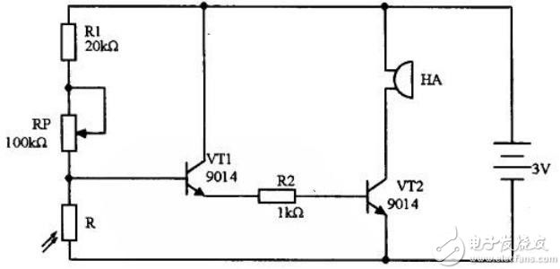
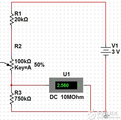
The picture above is a simple light-controlled alarm circuit, so let's analyze it and appreciate the wonderful electronic technology. First, we can see the right bright resistor R and the triodes VT1 and VT2 in the circuit, and the buzzer HA. Then we can probably guess that the working principle is because the R resistance changes, and the voltage change across the R resistance causes the triode state to change. , thus affecting the working state of the buzzer. In the multisim simulation software, the following circuit diagram is built. This is a resistor divider circuit. The larger the resistance of the photoresistor, the higher the voltage across it.
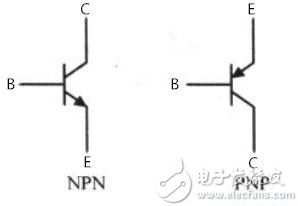
The key component in the light-controlled alarm circuit is the triode. For the composition of the triode, we find the textbook of Qin Zenghuang. In general, whether it is an NPN type or a PNP type transistor, there are three pins of a B base, a C collector, and an E emitter. Just as a diode is associated with a single-conductivity, when it comes to a triode, it is associated with "current amplification." Everyone compares a triode to a faucet in real life (B is a valve, C is a water tank, and E is a water pipe). It's easy to understand. Taking the NPN transistor as an example, when the voltage between the BE reaches the trigger voltage (0.7V), the faucet valve is opened, and the water in the water tank can flow to the water pipe. The specific flow rate is related to the degree of opening of the valve, that is, the triode acts on Amplification area; when the valve is opened to the maximum, the flow of water in the water tank to the water pipe is fixed, that is, the triode acts on the conduction area; of course, there is no water flow when the valve is closed, that is, the triode acts on the cut-off area.
Returning to the original light-controlled alarm circuit, when the resistance of the photoresistor increases to a certain value, the transistor VT1 is turned on (note that the conduction here is different from the "conduction" term in the operating characteristics of the triode, just to illustrate When the triode is opened to the faucet valve, there is a flow of water, as is the case with VT2 below. At this time, the collector current of VT1 flows to the emitter, that is, the current of the VT2 of the triode flows through the current, and the voltage is generated at the same time. Drop; if the transistor VT2 is turned on, the buzzer will sound.
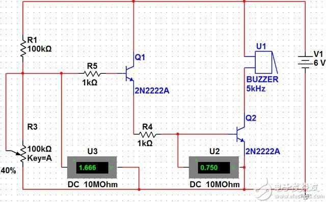
The schematic diagram built by multisim software is as follows. When we adjust the resistance of R3 (photosensitive resistor) to 40K, the base voltage of transistor Q2 is 0.75V, and the buzzer sounds awkward.
This 30 port USB charger can charge up to 30 iPad, iPhone, tablets, smartphones, or other USB devices to charge, which can identify your device and support the corresponding current to provide the fastest charging speed. And this 30 -port smart charger built -in intelligent multiple security protection to prevent your device from security such as excessive high, overvoltage, overload, etc.

30 Port Usb Charger,Red Intelligent Charger,30 Port Intelligent Charger,Usb Red Ai Smart Charger
shenzhen ns-idae technology co.,ltd , https://www.szbestchargers.com