The biggest problem for developers is that the core and non-core domains are not divided, and most of the time they are writing code that is not reusable and non-core. There is no focus on core domain knowledge that enhances product competitiveness, such as requirements, algorithms, user experience, and software engineering methods, resulting in much more code maintenance than initial development investment.
In fact, those teams that make great products not only have a very stable workforce, but also have a high income and even a different mental outlook. Because they use the right development strategies and methods, and the technology they master in a short period of time is far better than the so-called "old programmers." Although every company has high-paying employees, why not you? The products developed by others are sold, but the products you develop cannot be sold. Not only was it wasted the hard-earned funds, but it also led us to lose more opportunities to create greater value.
More than a decade ago, the author faced the same problem, so he did not hesitate to devote himself to the development of software and hardware standardization platform technology, because only the breakthrough of the method can create the future. AWorks was born in this context. Ametal, born out of Aworks-Nano subset, not only realizes cross-platform, but also defines the software interface standard of peripheral devices, so "on-demand" provides users with valuable services. It has become a reality.
Based on this, ZLG provides users with a large number of standard peripheral drivers and related protocol components, intended to build a complete ecosystem. No matter what MCU you choose, as long as you support AMetal, you can achieve "one-time programming, life-long use", the advantage is that you never reinvent the wheel.
6.1 E2PROM Memory
E 2 PROM (Electrically Erasable Programable Read-Only Memory) is a memory chip that does not lose data after power-off. This section uses FM24C02 as an example to describe in detail how to use similar in AMetal. Non-volatile memory.
> > > 6.1.1 Introduction to the device
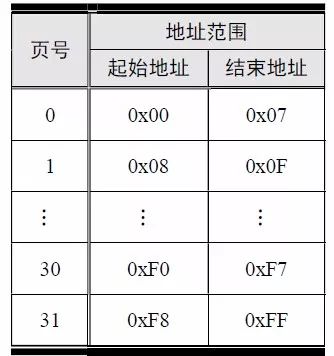
The total capacity of the FM24C02 is 2K (2048) bits, which is 256 (2048/8) bytes. Each byte corresponds to a memory address, so its address range for storing data is 0x00 ~ 0xFF. The size of the FM24C02 page is 8 bytes. Each write data cannot cross the page boundary, ie address 0x08, 0x10, 0x18...; if the write data crosses the page boundary, it must be written multiple times. The organizational structure is shown in Table 6.1.
Table 6.1 FM24C02 Memory Organization Structure
The communication interface of the FM24C02 is a standard I 2 C interface, requiring only two signal lines, SDA and SCL. Take the 8PIN SOIC package as an example here, as shown in Figure 6.1. The WP is write-protected, and when this pin is tied high, it will block all write operations. In general, this pin is directly grounded directly for proper chip reading and writing.
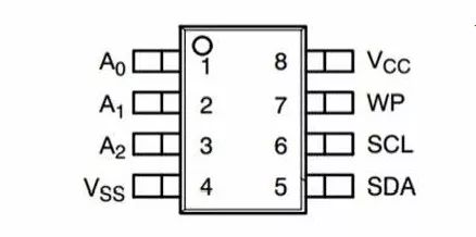
Figure 6.1 FM24C02 pin definition
A2, A1, and A0 determine the I 2 C slave address of the FM24C02 device, and its 7-bit slave address is 0101 0A2A1A0. If there is only one FM24C02 on the I 2 C bus, A2, A1, A0 are directly grounded and their address is 0x50.
In AMetal, since the user does not need to care about the control of the read/write direction bits, its address is represented by a 7-bit address. The MicroPort-EEPROM module is connected to the AM824-Core through the MicroPort interface. See Figure 6.2 for details. The E 2 PROM is the 256-byte FM24C02C provided by Fudan Micro-Semiconductor.
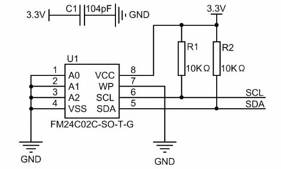
Figure 6.2 E 2 PROM circuit schematic
> > > 6.1.2 Initialization
AMetal provides drive functions for series I 2 C interface E 2 PROM supporting FM24C02, FM24C04, FM24C08, etc. The following is an example of FM24C02. The function prototype (am_ep24cxx.h) is:

This function is intended to get the device instance handle fm24c02_handle, where p_dev is a pointer to an instance of type am_ep24cxx_dev_t and p_devinfo is a pointer to instance information of type am_ep24cxx_devinfo_t.
Instance
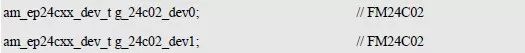
A single FM24C02 can be seen as an example of the EP24Cxx. The EP24Cxx simply abstracts an E 2 PROM chip representing a series or the same type. Obviously multiple FM24C02 are multiple instances of the EP24Cxx. If only one FM24C02 is externally connected to the I 2 C bus, an example of the am_ep24cxx_dev_t type (am_ep24cxx.h) is defined as follows:

Where g_at24c02_dev is a user-defined instance whose address is passed as an argument to p_dev. If two FM24C02s are connected to the same I 2 C bus, three instances need to be defined. which is:
Each instance is initialized, and each instance's initialization returns a handle to the instance. It is convenient to pass different instances of different handle operations when using other interface functions.
2. Instance information
The example information mainly describes the information specific to the specific device, that is, the slave address and specific model of the I 2 C device. The definition of the type am_ep24cxx_devinfo_t (am_ep24cxx.h) is as follows:
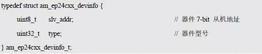
The currently supported device models have corresponding macros defined in am_ep24cxx.h. For example, the macro corresponding to FM24C02 is AM_EP24CXX_FM24C02, and the instance information is defined as follows:
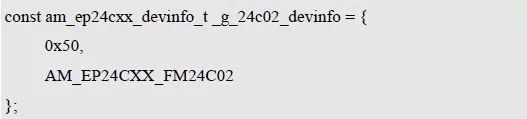
Where g_24c02_devinfo is user-defined instance information whose address is passed as an argument to p_devinfo.
3. I 2 C handle i2c_handle
Taking I 2 C 1 as an example, the return value of its instance initialization function am_lpc82x_i2c1_inst_init() is passed as an argument to i2c_handle. which is:

4. Example handle fm24c02_handle
FM24C02 initialization function am_ep24cxx_init () return value fm24c02_handle, passed as an argument to the read and write data function, its type am_ep24cxx_handle_t (am_ep24cxx.h) is defined as follows:

If the return value is NULL, the initialization fails; if the return value is not NULL, a valid handle is returned.
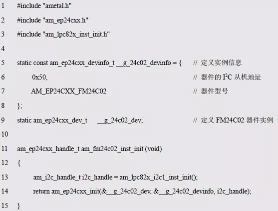
Based on the modular programming idea, the definitions of the initialization related instance and instance information are stored in the corresponding configuration file, and the instance initialization function interface is extracted through the header file. The program examples of the source file and the header file are respectively shown in the program list 6.1 and the program. Listing 6.2.
Listing 6.1 Example Initialization Function Sample Program (am_hwconf_ep24cxx.c)
Listing 6.2 Instance Initialization Function Interface (am_hwconf_ep24cxx.h)
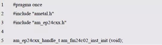
Subsequent only need to use the parameterless instance initialization function to get the instance handle of FM24C02. which is:

Note that i2c_handle is used to distinguish I 2 C 0, I 2 C 1 , I 2 C 2, I 2 C 3, and the initialization function return value instance handle is used to distinguish between multiple devices connected in the same system.
> > > 6.1.3 Reading and writing functions
The function prototypes for reading and writing the EP24Cxx series memory are shown in Table 6.2.
Table 6.2 ep24cxx read and write functions (am_ep24cxx.h)
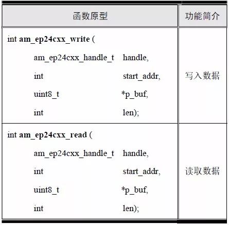
The return value of each API has the same meaning: AM_OK means success, negative value means failure, and the reason for failure can be based on the specific value to view the corresponding macro definition in the am_errno.h file. The meaning of positive values ​​is defined by each API. If there is no special explanation, it means that it will not return a positive value.
1. data input
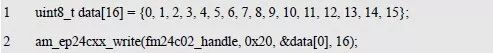
The function prototype for writing a piece of data starting from the specified starting address is:

If the return value is AM_OK, the write is successful, otherwise it fails. Assume that 16 bytes are written consecutively starting from the 0x20 address, as detailed in Listing 6.3.
Listing 6.3 Write Data Sample Program
2. Read data
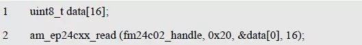
The function prototype for reading a piece of data starting from the specified starting address is:
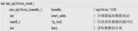
If the return value is AM_OK, the read is successful, otherwise it fails. Assume that 16 bytes are read consecutively starting from the 0x20 address, as detailed in Listing 6.4.
Listing 6.4 Read data sample program
As shown in Listing 6.5, write 20 bytes of data and read it out, then compare the same examples.
Listing 6.5 FM24C02 Read and Write Sample Program
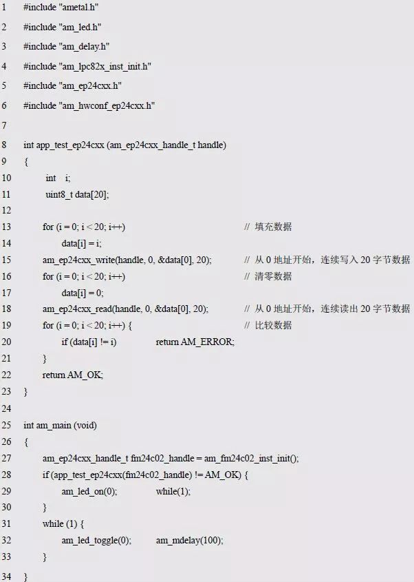
Since the parameter of app_test_ep24cxx() is an instance handle, it has a dependency on the EP24Cxx device, so cross-platform calls cannot be implemented.
> > > 6.1.4 NVRAM Universal Interface Functions
Since the E2 PROM such as the FM24C02 is a typical nonvolatile memory, reading and writing data using the NVRAM (nonvolatile memory) standard interface does not require care for a specific device. Before using these interface functions, set the value of the AM_CFG_NVRAM_ENABLE macro of the project configuration am_prj_config.h to 1, and the related function prototype is shown in Table 6.3.
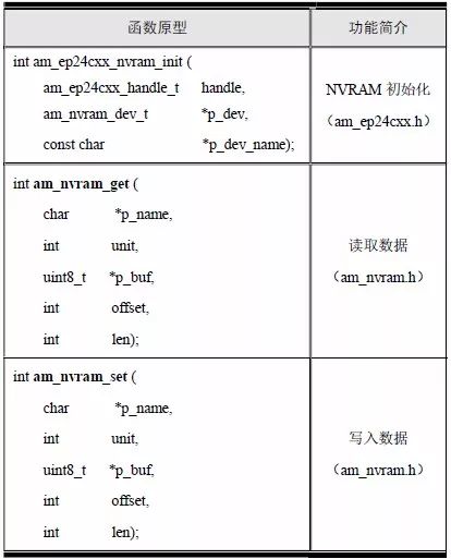
Table 6.3 NVRAM Common Interface Functions
1. Initialization function
The NVRAM initialization function is intended to initialize the NVRAM function of the FM24C02 to read and write data using the NVRAM standard interface. Its function prototype is:
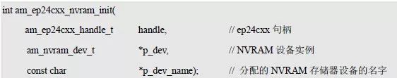
The ep24cxx instance handle fm24c02_handle is passed as an argument to the handle, p_dev is a pointer to the am_nvram_dev_t type instance, and p_dev_name is an NVRAM device name assigned to the FM24C02, so that other modules can locate the FM24C02 memory by this name.
(1) Example (NVRAM memory)
NVRAM abstractly represents all nonvolatile memory, and the FM24C02 can be considered as a specific example of NVRAM memory. Define an example of the am_nvram_dev_t type (am_nvram.h) as follows:

Where g_24c02_nvram_dev is a user-defined instance whose address is passed as an argument to p_dev.
(2) Instance information
The instance information contains only one device name specified by the p_dev_name pointer. The device is named a string such as "fm24c02". After initialization, the name uniquely identifies an FM24C02 memory device. If there are multiple FM24C02, it can be named "fm24c02_0", "fm24c02_1", "fm24c02_2"...
Based on the modular programming idea, the code that initializes the FM24C02 to the standard NVRAM device is stored in the corresponding configuration file, and the corresponding instance initialization function interface is extracted through the header file. See Listing 6.6 and Program Listing 6.7 for details.
Listing 6.6 adds the NVRAM instance initialization function (am_hwconf_ep24cxx.c)
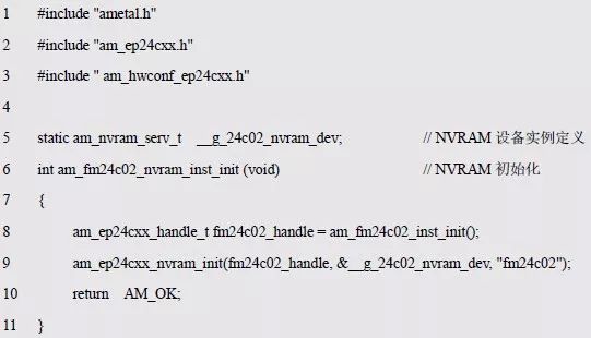
Listing 6.7 am_hwconf_ep24cxx.h file update

Subsequently, you only need to use the parameterless instance initialization function to complete the NVRAM device initialization and initialize the FM24C02 to an NVRAM storage device named "fm24c02". which is:

2. Storage segment definition
NVRAM defines the concept of a bucket, and both read and write functions operate on specific buckets. NVRAM memory can be divided into single or multiple segments. The type of the storage segment am_nvram_segment_t is defined as (am_nvram.h) as follows:
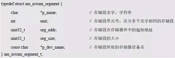
The name of the bucket p_name and the unit number unit can uniquely identify a bucket. When the names are the same, the unit number is used to distinguish different buckets. The name of the storage segment gives each storage segment an actual meaning. For example, a storage segment named "ip" represents a storage segment that holds an IP address, and a storage segment named "temp_limit" represents a storage temperature upper limit value. Storage segment. Seg_addr is the starting address of the storage segment in the actual storage, and seg_size is the capacity of the storage segment. P_dev_name indicates the name of the actual storage device corresponding to the bucket.
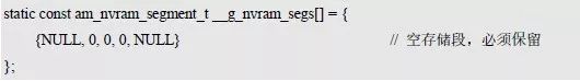
To assign a bucket to the FM24C02, set p_dev_name in the bucket to "fm24c02". Subsequent read and write operations for this segment are actually reading and writing operations on the FM24C02. For the convenience of management, all storage segments are uniformly defined in the am_nvram_cfg.c file. By default, the storage segment is empty, which is defined as:
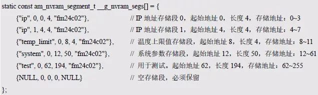
After you have the FM24C02 storage device, you can add some segment definitions. For example, the application needs to use 4 storage segments to store 2 IP addresses (4 bytes × 2), temperature upper limit (4 bytes) and system. The parameter (50 bytes), the corresponding bucket list (array of bucket information) is defined as follows:
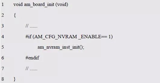
In order for the bucket to take effect, the am_nvram_inst_init() function (am_nvram_cfg.h) must be called at system startup. The function prototype is:

This function is often called in the board-level initialization function, which can be clipped by the AM_CFG_NVRAM _ENABLE macro in the project configuration file (am_prj_config.h), as shown in Listing 6.10.
Listing 6.8 Initializing NVRAM in board level initialization
After NVRAM is initialized, according to the storage segment defined in the am_nvram_cfg.c file, a total of 5 storage segments are added. Their names, unit numbers and sizes are respectively shown in Table 6.4. The general NVRAM read/write interface pair can be used later. These segments are read and written.
Table Nev. NVRAM buckets defined in Table 6.4

3. data input
The prototype of the write data function is:

Among them, p_name and unit respectively represent the name and unit number of the storage segment, determine the storage segment for writing data, p_buf provides data to be written to the storage segment, offset indicates that data is written from the offset specified by the storage segment, and len is written. The length of the data. If the return value is AM_OK, the write is successful, otherwise it fails. For example, save an IP address to an IP bucket, as described in Listing 6.9.
Listing 6.9 Write Data Sample Program

4. Read data
The prototype of the read data function is:

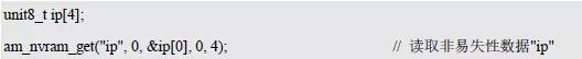
Where p_name and unit are the name and unit number of the storage segment, respectively, to determine the storage segment for reading data; p_buf holds the data read from the storage segment, offset indicates that the data is read from the offset specified by the storage segment, and len is read. Take the length of the data. If the return value is AM_OK, the read is successful, otherwise it fails. For example, read the IP address from the IP bucket, as shown in Listing 6.10.
Listing 6.10 Read Data Sample Program
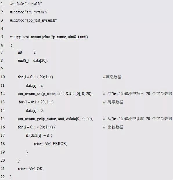
Now write a simple test program for the NVRAM general interface to test whether the data read and write of a certain segment is normal. Although the test program is a simple application, based on the modular programming idea, it is best to separate the test-related programs. The program implementation and corresponding interface declarations are detailed in Listing 6.11 and Listing 6.12.
Listing 6.11 Test program implementation (app_test_nvram.c)
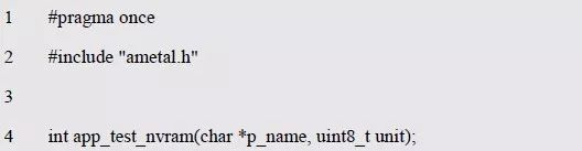
Listing 6.12 Interface Declaration (app_test_nvram.h)
The memory segment (segment name and unit number) to be tested is passed to the test program by parameters, and the NVRAM general interface reads and writes data to the test segment. If the result of reading and writing data is completely equal, AM_OK is returned, otherwise AM_ERROR is returned.
It can be seen that the implementation of the application does not contain any device-related statements. It only calls the NVRAM general interface to read and write the specified memory segment. Therefore, the application is cross-platform and can be used in any AMetal platform to further integrate NVRAM. Examples of interfaces and test procedures are detailed in Listing 6.13.
Listing 6.13 NVRAM Universal Interface Read and Write Sample Program

Obviously, the NVRAM universal interface gives the storage section of the name, making the program superior to the EP24Cxx read-write interface in terms of readability and maintainability. Calling the NVRAM common interface consumes a certain amount of memory and CPU resources, especially in applications where high efficiency or memory shortage is required. The EP24Cxx read/write interface is recommended.
Outdoor Cable,Outdoor Power Cable,Outdoor Power Cord,Outside Cable
Huizhou Fibercan Industrial Co.Ltd , https://www.fibercannetworks.com