Capacitor three-point oscillator circuit
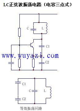
This circuit is ideal for generating high-frequency signals, typically above tens of megahertz, and is widely used in radio frequency applications. The second image shows the equivalent circuit of an LC oscillation setup. As seen from the diagram, the oscillation frequency depends on L, C, C1, and C2. Additionally, the base has a large capacitance (ranging from 1000 to 2000 pF), which acts as an AC ground. When the values of inductors and capacitors are small, the inter-electrode capacitance of the transistor and the inter-turn capacitance of the inductor can't be ignored. These contributions can add up to a few picofarads in some cases.
To simplify calculations, we can assume that the total equivalent capacitance from all distributed sources, including the transistor's inter-electrode capacitance and the inductor's inter-turn capacitance, is C0 = 2 pF.
The capacitor three-point oscillator is also known as the Colpitts oscillator. As shown in Figure Z0808, its structure is similar to the inductor-based three-point oscillator, but with the roles of inductors and capacitors swapped. A resistor RC is added to provide a DC path for the collector circuit. The AC path of this circuit is illustrated in Figure Z0809, where it follows the "same base" principle of the three-point oscillator and satisfies the phase condition for self-excitation.
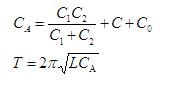
Under the condition that the Q value of the LC resonant circuit is sufficiently high, the oscillation frequency of the circuit can be calculated using the formula:

where:
This type of oscillator is known for its ability to generate higher frequencies, typically up to 100 MHz.
One advantage of this circuit is that the higher harmonics of C2 have low impedance, which reduces the presence of harmonic components in the feedback voltage, resulting in a cleaner waveform. However, a disadvantage is that adjusting the frequency is not very convenient. Even if variable capacitors like C1 and C2 are used, it's difficult to scale them properly, leading to instability in the circuit performance. Therefore, this circuit is best suited for fixed-frequency applications.
A three-point capacitor circuit using an operational amplifier is shown in Figure Z0810. It can be proven that the oscillation frequency of this configuration is given by:
Off-Grid Solar Inverter,Mppt Charger,Multi-Function Inverter,High Frequency Inverters
Shenzhen Unitronic Power System Co., Ltd , https://www.unitronicpower.com