Universal signal collector based on Xilinx FPGA

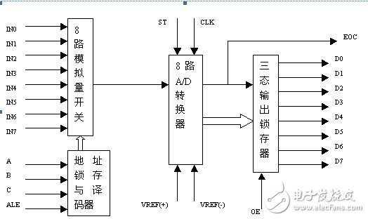
In the previous article, I wrote a general signal generator based on Xilinx FPGA. The response is better. Many friends and I discussed related technologies, including the signal acquisition. In order to make the article more flesh and blood, I am writing a The general signal collector of Xilinx FPGA hopes to form an echo to answer your questions. Purpose: 1. Through the design to achieve signal acquisition and analysis, master the combination logic design method; 2. Through the design to achieve signal acquisition and analysis, master the principle of signal acquisition. Principle: Using FPGA chip, write logic in verilog language, control AD0809 for AD conversion. The AD0809 is a CMOS component with an 8-bit AD converter, 8-way multiplexer, and microprocessor-compatible control logic. It is a successive approximation AD converter. The internal structure of AD0809 is as follows:

Universal signal collector based on Xilinx FPGA

As can be seen from the above figure, the multiplexer can select 8 analog channels, allowing 8 analog time-sharing inputs, sharing the AD converter for conversion, and the 3-state output latch is used to latch the digital quantity after the AD conversion is completed. The converted data can be taken out of the latch when OE is high. The channel selection is shown below:

Universal signal collector based on Xilinx FPGA

START is the conversion start signal. When the START is on, all internal registers are cleared; on the next edge, A/D conversion begins; during the conversion, START should be held low. EOC is the end of conversion signal. When EOC is high, it indicates the end of the conversion; otherwise, it indicates that A/D conversion is in progress. OE is an output enable signal for controlling the data output from the three output latches to the microcontroller output. OE=1, output converted data; OE=0, the output data line is in a high impedance state. The timing is shown below:

Universal signal collector based on Xilinx FPGA

Source code 1.Verilog source code, dataCollect.vmodule dataCollect(sysclk, rst, adda, addb, addc, start, oe, datain, led_sel, led_seg); input sysclk, rst; input wire [7:0] datain; output reg Adda, addb, addc, start, oe; output reg[3:0] led_sel; output reg[7:0] led_seg; reg [3:0] counter1; reg [7:0] readdata; reg [9:0] Counter2; reg [15:0] sum; reg [7:0] averdata; reg [7:0] temp; reg [3:0] dataout1, dataout2, dataout3; reg [3:0] counter3; parameter ZERO = 8 'b11111100, ONE = 8'b01100000, TWO = 8'b11011010; parameter THREE = 8'b11110010, FOUR = 8'b01100110; parameter FIVE = 8'b10110110, SIX = 8'b10111110, SEVEN = 8'b11100000; parameter EIGHT = 8'b11111110, NINE = 8'b11110110, BLANK = 8'b00000000; always @(posedge sysclk or negedge rst) begin if (!rst) begin adda = 0; addb = 0; addc = 0; oe = 1; counter1 = 0; end else begin c Ounter1 = counter1 + 1; case (counter1) 3 : start = 0; 4 : start = 1; 5 : start = 0; 10 : readdata = datain; 15 : counter1 = 0; default : counter1 = counter1; endcase end end always @(posedge sysclk or negedge rst) begin if (!rst) begin counter2 = 0; sum = 0; averdata = 0; end else begin counter2 = counter2 + 1; if ((counter2%16) == 0) sum = sum + readdata; else if (counter2 > 512) begin averdata = sum / 32; sum = 0; counter2 = 0; end end end always @(averdata) begin temp = averdata; if (temp > 199) dataout3 = 2; else if (temp > 99) dataout3 = 1; else dataout3 = 0; temp = temp - dataout3 * 100; if (temp > 89) dataout2 = 9; else if (temp > 79) dataout2 = 8; else if (temp > 69) dataout2 = 7; else if (temp > 59) dataout2 = 6; else if (temp > 49) dataout2 = 5; else if (temp > 39) dataout2 = 4; else if (temp > 29) dataout2 = 3; else if (temp > 19) dataout2 = 2; else if (temp > 9) dataout2 = 1 ; else dataout2 = 0; temp = temp - dataout2 * 10; dataout1 = temp; if ((dataout3==0) && (dataout2==0)) begin dataout3 = 10; dataout2 = 10; end else if (dataout3 == 0) dataout3 = 10; else dataout3 = dataout3; end always @(posedge sysclk or negedge rst) begin if (!rst) begin counter3 = 0; led_sel = 4'b0001; end else begin if (count Er3 == 4) begin counter3 = 0; if (led_sel == 4'b1000) led_sel = 4'b0001; else led_sel = led_sel << 1; end counter3 = counter3 + 1; end end always @(led_sel, dataout1, dataout2 , dataout3) begin case (led_sel) 4'b0001 : begin case (dataout1) 0 : led_seg = ZERO; 1 : led_seg = ONE; 2 : led_seg = TWO; 3 : led_seg = THREE; 4 : led_seg = FOUR; 5 : led_seg = FIVE; 6 : led_seg = SIX; 7 : led_seg = SEVEN; 8 : led_seg = EIGHT; 9 : led_seg = NINE; default : led_seg = BLANK; endcase end 4'b0010 : begin case (dataout2) 0 : led_seg = ZERO; 1 : led_seg = ONE; 2 : led_seg = TWO; 3 : led_seg = THREE; 4 : led_seg = FOUR; 5 : led_seg = FIVE; 6 : led_seg = SIX; 7 : led_seg = SEVEN; 8 : Led_seg = EIGHT; 9 : led_seg = NINE; default : led_seg = BLANK; endcase end 4'b0100 : begin case (dataout3) 0 : led_seg = ZERO; 1 : led_seg = ONE; 2 : led_seg = TWO; 3 : led_seg = THREE 4 : led_seg = FOUR; 5 : led_seg = FIVE; 6 : led_seg = SIX; 7 : led_seg = SEVEN; 8 : led_seg = EIGHT; 9 : led_seg = NINE; default : led_seg = BLANK; endcas e end 4'b1000 : begin case (10) 0 : led_seg = ZERO; 1 : led_seg = ONE; 2 : led_seg = TWO; 3 : led_seg = THREE; 4 : led_seg = FOUR; 5 : led_seg = FIVE; 6 : led_seg = SIX; 7 : led_seg = SEVEN; 8 : led_seg = EIGHT; 9 : led_seg = NINE; default : led_seg = BLANK; endcase end default : begin led_seg = 1'hx; end endcase end endmodule 2. Pin assignment source code, dataCollect.ucfnet sysclk loc = p80; net rst loc = p57; net adda loc = p14; net addb loc = p16; net addc loc = p18; net oe loc = p23; net start loc = p27; net datain<7> loc = p30;net datain<6> loc = p33;net datain<5> loc = p35;net datain<4> loc = p37;net datain<3> loc = p42;net datain<2> loc = p44;net datai n<1> loc = p46;net datain<0> loc = p48; net led_sel<3> loc = p3;net led_sel<2> loc = p5;net led_sel<1> loc = p7;net led_sel<0> loc = p9; net led_seg<7> loc = p206;net led_seg<6> loc = p204;net led_seg<5> loc = p202;net led_seg<4> loc = p200;net led_seg<3> loc = p195;net led_seg <2> loc = p193; net led_seg<1> loc = p191; net led_seg<0> loc = p187; OK, can be used, according to the pin assigned to the device, the system clock input is even 1KMHZ, can Rotate the potentiometer to change the input voltage, and the data change on the data tube can be observed. FPGA, integrated into it, is fun. . . .

Electric Irons

Electric iron is a tool for leveling clothes and fabrics, and its power is generally between 300-1000W. Its types can be divided into: ordinary type, temperature adjustment type, steam spray type and so on. Ordinary electric irons are simple in structure, low in price, and convenient to manufacture and maintain. The temperature-regulating electric iron can automatically adjust the temperature within the range of 60-250℃, and can automatically cut off the power. It can be ironed at a suitable temperature according to different clothing materials, which is more power-saving than the ordinary type. Steam spray type electric irons not only have the function of temperature adjustment, but also generate steam. Some are also equipped with a spray device to avoid the trouble of manual water spraying, and the clothes are more evenly moistened and the ironing effect is better.

ShenZhen YouTai Imp.& Exp. Co., Ltd. founded in 2014, headquartered in Shenzhen, which is a leading supplier of high-tech ODM/OEM One-Stop services for smart Home Appliances, Kitchen Appliances, Consumer Electronics.Our strategic partnership have TCL, Skyworth, Lenovo and Medea. Our customers are from more than 10 countries. We committed to manufacture and provide customers high performance and high value of innovative electronic products.Welcome to inquiry about us!


Mini Electric Irons,Household Electric Irons,Portable Electric Irons

Shenzhen YouTai Imp.&Exp.,Co.,Ltd. , https://www.szyoutai-tech.com