The use of power electronic components will continue to increase for the foreseeable future. Any form of power electronics must be used for any function that requires power conversion, conversion or control. Today's power electronic components have been widely used in a variety of different industries (Figure 1). The gray circle represents the industries that need to use power modules, such as the automotive industry (electric vehicles, hybrid vehicles, fuel cell vehicles and other wheeled vehicles), renewable energy industry (solar inverters, wind turbines, solar energy). Power stations, satellite solar panels), railway facilities (engine components, traction control systems) and high-end motor drives. These power electronic components typically consist of a variety of insulated gate bipolar transistors (IGBTs) or metal oxide semiconductor field effect transistors (MOSFETs).
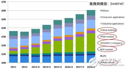
Figure 1 Application of power electronics. Gray circles indicate industries that must use high power modules. In the high-power electronics industry, the demand for power electronic components in electric vehicles, hybrid vehicles and their charging stations has increased significantly.
Power component reliability challenges multiply
For users using IGBTs or power MOSFETs, reliability is their primary concern. In these industries, the high reliability and long service life of the product are especially important. Users expect electric vehicles to not experience any major maintenance problems for 15 to 20 years; the railway industry must continue to use for at least 30 years or more. It is obviously not feasible to dispatch maintenance personnel to repair offshore wind turbines from time to time. Satellite solar panels must even be used permanently.
Thermal failure is the main cause of high reliability. The power cycle causes the heat generated at the IGBT chip end to pass through the module and is dissipated into the surrounding environment, and the stress and heat generated by it can damage the module. The wire bond may fall off or break due to fatigue aging, and even worse, leading to complete failure (Figure 2). The stacked layers of the module, especially the wafer solder joints, are delaminated and broken due to thermal-structural stress. These modules can withstand tens of thousands or even millions of power cycles before they fail completely.
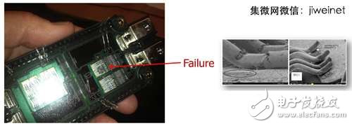
Figure 2 There are many reasons for IGBT module failure, including wire aging or shedding.
So how do we guarantee that these modules will last for many years in their applications and withstand thousands of power cycles? This is not only the responsibility of the power electronics module supplier, but also the problem that the relevant industry suppliers must overcome. Whether it is the initial component supplier or the original equipment manufacturer (OEM) is duty-bound. If the power module produced is damaged too early, the OEM should bear the loss of warranty, product recall, reputation damage, etc.
Reliability testing of power modules is not a new challenge, but the traditional module testing process is very lengthy and inaccurate and uncertain (Figure 3). The general reliability test will install the IGBT module on the device and provide the specified amperage for power cycling testing. After multiple power cycle tests (500, 1,000, 5,000, etc.), the user must remove the module from the device and send it to the laboratory for verification to see if there is any fault. If there is no fault, continue to repeat the loop test until the module eventually fails. At this point the module will be sent to the laboratory for inspection to determine the cause of the malfunction by X-ray, acoustic, visual or destructive anatomy.
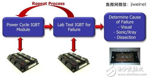
Figure 3 The traditional IGBT module reliability test method is time-consuming and low-accuracy. It is impossible to observe the failure during the test and can only determine whether the final product is invalid.
Repeated power cycling tests and laboratory tests are time consuming and do not allow for immediate observation of failures during the test, only to determine if the component has failed. If the failure is caused by many different reasons, the exact cause may not be determined.
New reliability test methods came into being
We need a test that is more effective and quick to determine the cause of failure. This method is required to measure the electrical/thermal effects in the module during the power cycle test and to immediately identify the cause of the failure rather than relying on the subsequent diagnosis. In order to meet the above requirements, only the power cycle and measurement can be integrated into the same device, so that the user does not need to take the module out of the power cycle test equipment and send it to the laboratory for failure analysis. Mentor Graphics' new MicReD Industrial Power Tester 1500A provides such a test environment.
4 is a schematic diagram of power cycling and power measurement/diagnosis of a power test device. The test equipment uses MicRed T3Ster transient thermal characterization technology to measure components (such as chip packages, LEDs, and systems). The main features are:
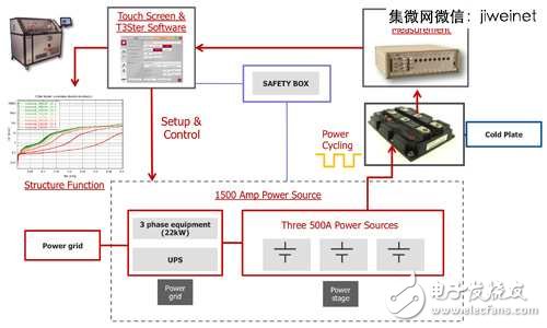
Figure 4 Test equipment integrates power cycling and real-time measurement methods to instantly monitor module failures and reduce post-mortem analysis in the lab.
. Use touch screen to control, define module characteristics and test sequence and method
Whether it is an expert, product engineer or technician, you can easily learn and use it. The software can store relevant parameters for reuse and can be used to test sample or product quality reliability on multiple production lines.
. The 1500 amp power supply can be tested simultaneously with three different modules, each capable of using up to 500 amps of current.
The power switching time is less than 100 microseconds, which is the speed required by the T3Ster device for high accuracy transient thermal characteristics testing.
. During the loop test, the user can define the time interval to measure and record the forward voltage change of the module. The maximum sampling rate is up to one million samples per second.
These data will be displayed on the touch screen and directly generate a structure function.
. The structure function can be used to analyze the structure of each layer of the module in real time, and to find any changes that may occur due to failure (wafer or adhesive layer detachment, cracking, etc.).
This information can help determine the exact time and cause of the failure.
. The safety box monitors for any potential hazards such as smoke, cold plate fluid leaks, and equipment overheating.
Once these factors are detected, the test equipment will immediately turn off all power; however, to save the test data, the UPS will continue to power the computer until all data is safely stored.
Xinxiang Mina Import & Export Co., Ltd. , https://www.mina-motor.cn