Abstract: In order to meet the needs of miniaturization and digitization of modern acquisition systems, a digital image acquisition system based on DaVinci technology DSP chip is designed. This design method does not require an external codec chip, directly connected to the digital camera, reducing the image interference caused by D/A conversion, and utilizes the integrated video processing subsystem component (VPSS) on the Delphich series DSP. The video processing front end (VPFE) simplifies the software design by performing image preprocessing operations such as video capture, CFA interpolation, and color space interpolation on digital video images in hardware. The results show that the video images collected by the system are clear, stable, and color balanced, meeting the requirements of ordinary cameras for video images.
Keywords: digital camera; video capture; DM6437; VPFE
With the development of society, video surveillance has been applied in the fields of transportation, finance, electric power, home, public security, fire protection, etc. The technology and means of video surveillance are constantly developing and improving. The key component of the camera is the image sensor. At present, image sensors are mainly divided into CCD and CMOS types. CCD sensors are superior to CMOS sensors in terms of sensitivity, resolution, and noise control, while CMOS sensors have low cost, low power consumption, and high integration. Features. However, with the advancement of CCD and CMOS sensor technology, the difference between the two has gradually narrowed. The video image processing chip used in the video surveillance system is mainly DSP, and the powerful data calculation capability of the DSP chip can complete many complicated algorithms. TI also released the Da Vinci series of DSP chips for image processing. The chip integrates a video processing subsystem dedicated to video capture and display, which greatly facilitates user video capture and video display.
1 Camera working principle and key technical description Digital camera refers to the digital image signal collected by the image sensor directly transmitted to the image processing chip at the back end for processing, without digital/analog, analog/digital conversion of digital image signals of traditional analog cameras. The process, thus avoiding the effects of noise caused by the image signal digital-to-analog conversion process. The Bayer format digital image signal sent by the image sensor will be directly captured by the image processing chip of the back end, and then the captured video signal is subjected to CFA interpolation, color space conversion and the like. Finally, the video image in the YUV format is generated, and the generated YUV format video image can be stored or sent to the network through the network port.
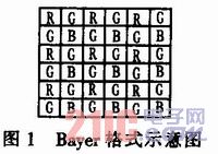
Bayer format: Each pixel in the photosensitive area of ​​the CMOS image sensor senses a color, where R senses red light, G stands for green light, and B senses blue light. The odd line scan output is R, G, R, G..., and the even line scan output is G, B, G, B.... Its format is shown in Figure 1.
This article refers to the address: http://
CFA interpolation: Bayer format image signal represents only one color per pixel, and pixel color requires 3 primary colors for representation. Interpolation of image signals in Bayer format is required. The output image is linearly averaged using the same color components in adjacent pixels. Compensate for the missing color of each pixel. Finally, each pixel is represented by three colors of R, G, and B, that is, a so-called RGB format image.
Color space conversion: In the processing of graphic images, the efficiency of RGB is not very high, because in any color, R, G, B 3 need the same bandwidth, need to modify the brightness and chromaticity of the pixel All three were revised. The YUV color space describes the concept of luminance and chrominance, Y refers to brightness, U refers to hue, and V refers to saturation. The conversion relationship of color space is shown in Figure 2.

2 Camera hardware components Digital cameras are mainly composed of image sensors, DSP chips and displays. The overall block diagram of the system is shown in Figure 3.
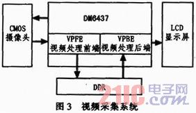
The CMOS camera is mainly used to perform photoelectric conversion of image information, and the output signal is a digital Raw Bayer mode image signal. The output Bayer mode image signal will enter the video processing subsystem directly through the video processing front end (VPFE) video input port. The video processing front end stores the received video signal and stores it. Since a large amount of video image data needs to be stored, the memory capacity needs to be large enough. TI specially designed a 32-bit, 256 Mbyte high-speed, large-capacity DDR2 memory for high-speed storage of video image data. The video processing back end (VPBE) reads the video image signal stored in DDR2 and transmits it to the display for display through the video output port.
3 TMSDM6437 DSP hardware structure TMS320DM6437 is a series of processors developed by TI to develop high-performance, low-cost video applications with a 600MHz, 32-bit fixed-point DSP DaVinci technology. The DM643 7 uses a 2-level CaChe memory architecture with a 64-channel enhanced DMA controller EDMA on-chip to support complex data type transfers, facilitating efficient image data transfer and format conversion. The DM6437 includes a rich external memory interface and a rich peripheral interface for easy communication with other devices.
The video input/output interface on the DM6437 is collectively referred to as the video processing subsystem VPSS. The video processing subsystem of the DM6437 consists of two parts: 1 is the video processing front end (VPFE) for inputting digital video data for multiple standard digital video. The input provides an interface and performs the necessary pre-processing for the input digital video data; 2 is a video processing back end (VPBE) for outputting video data to drive the display to display the video image. The VPSS functional structure diagram is shown in Figure 4.
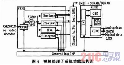
1) Video Processing Front End The VPFE DM6437 Video Processing Front End (VPFE) provides two major functions for video processing systems. One is to provide a seamless interface for multiple standard digital video inputs, and the other is to provide the necessary preprocessing for various video processing applications.
CCDC is a digital video input interface, which can be directly connected to the CMOS camera, supports Bayer BGB image format input or analog video signal is converted to 8//10 bit BT by codec chip. 656 or 8/16 line position YUV4:2:2 digital video stream with line and field sync signals.
The previewer (Priview) is used for video input in Bayer RGB mode. The video data of Bayer RGB image format is converted into YUV4:2:2 image format by hardware.
The Resizer accepts video data from the previewer, CCDC controller or memory to achieve image size scaling from 1/4 to 4 times.
The H3A is Auto Focus, Auto White Blanee, and Auto Exposure. H3A can only be used for Raw Bayer mode data. Autofocus, auto white balance and auto exposure can be done by hardware by selecting the corresponding matrix.
The Histogram is used to perform histogram statistics on various color information in a video image.
2) Video Processing Backend VPBE DM6437 Video Processing Backend (VPBE) is used to implement video image output display, including OSD module and VENC module.
The OSD (On-Screen Display) module is mainly used to combine video data, graphics and characters from different sources into the same digital video stream, and then output the combined video stream to VENC in YebCr format.
VENC (Video Encode) mainly has three modules: the video encoding module will generate analog video data output, the digital LCD controller will generate digital RGB/YChCr data output and the required timing signals, and the timing generator module will generate the video encoding module and data LCD. Input and output clock signals required by the controller module.
4 camera running process
4.1 Video Processing Front End (VPFE) Processing For the VPFE components integrated on the DM6437 chip, we mainly use the CCD controller and the previewer module. The CCD controller receives the external video signal as an interface, and the previewer converts RGB to YChCr. The main image processing module of its internal setting is shown in Figure 5.
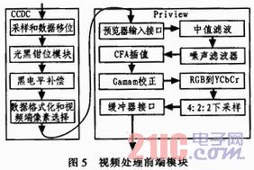
For the CCD controller (CCDC), the sample and data shift block is used to set the latch, data clock polarity, and CCD pixel data width selection. The light black clamp module is used to remove noise from the image data frame. Black pixel compensation is used to adjust the signal level of each color channel. Data formatting and video side pixel selection are used to set the length of the line/field sync signal, as well as the format of the image data frame from this sensor, reflecting the read frame structure of the sensor.
For the Previewer, the Previewer interface is used to select the interface direction of the video source and set the size of the input frame. Median filtering and noise filtering are used to filter out noise in the image data. CFA interpolation is used to convert Bayer mode RGB image format data to RGB data format. Gamma correction is used to adjust the nonlinear characteristics of the video image machine display. RGB to YCbCr is used to convert the image from the RGB color space to the YCbCr color space. The 4:2:2 downsampling module converts the image data into the YCbCr4:2:2 format. The buffer interface is used for the flow of image data. If it is SDRAM, the start address of the SDRAM and the row offset address need to be set.
4.2 System Operation Process The operation process of the whole system is mainly the initialization of the system and the configuration of the video port. The main operation process is shown in Figure 6.
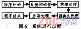
Before running the entire video acquisition system, you need to define the pins of the DSP chip. Because most of the pins of the DSP are multiplexed pins, the function of the chip pins and the output signal need to be determined according to the requirements. The foot definition is determined by setting the internal PINMUX1 and PINMUX2 registers of the chip, so the chip initialization function needs to be run first.
System initialization: Mainly used to initialize the system clock of DM6437, DDR2 clock, memory space allocation of L2 cache, external memory space mapping and multiplexed pin assignment.
Front-end processing: used to configure the CCDC to be a 10-bit Raw Bayer mode interface, receive raw data from the digital camera, and define the resolution of the video image to be 720x576. The optical black clamp module and the black level compensation module are enabled, and finally the video output resolution of the CCDC and the data path flow to the previewer are set. In the previewer interface module. The set interface accepts 10-bit Raw Bayer mode image data from CC-DC, and selects image data in the buffer interface module to be popular as external memory DDR2, specifying an image storage address and an offset address.
Camera configuration: CMOS camera is configured via the I2C bus. The PLL setting register needs to be configured, and the set clock signal is used as the pixel output clock. Secondly, it is necessary to set the image format register and some control registers, which are mainly used for the gain of analog signals, the gain of digital signals, the black level correction, and the digital offset correction registers. The setting of these registers can make the image signals we get more ideal. .
Backend processing: used to configure the video processing backend (VPBE). According to the setting of VPFE, VPBE sets the same video picture resolution, and the image memory read address in VPBE is the image storage address in VPFE. In the display window selection, select the display window as video windou0, and disable other display windows. Set the output signal to a composite video signal (CVBS signal) made by NTSC.
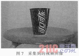
5 Test results The resolution of the camera in the video capture system is set to 720x576, and the captured video image is shown in Figure 7. Observing the captured video images, the picture is clear, the frame number is stable, and the color is balanced, which satisfies the requirements of ordinary cameras and network cameras for video images. When the resolution needs to be changed, only the corresponding register settings in the program can be changed, and the hardware does not need to be changed, which reduces the development cost.
6 Conclusion In this paper, DaVinei technology processor TMSDM6437 chip is used to realize digital video image acquisition. This method makes full use of the integrated components on the series of chips - the video processing subsystem, completes the video image data acquisition and some image pre-processing operations in hardware, so that only the image extraction and recognition are performed later, without The operation of converting, encoding and decoding image data simplifies the design of such a system. Because the video processing subsystem is a hardware-integrated component on the chip that runs fast, these are guaranteed for small, real-time digital acquisition systems.
Single Wall Electric Water Boiler Urn
Single wall electric water boiler urn
Single wall electric water boiler urn
FOSHAN FORTUNE ELECTRICAL APPLIANCE CO.,LTD , https://www.coffelady.com