1 Introduction
Ultrasonic directivity, slow energy consumption, and long distances in the medium are used for distance measurement. Ultrasonic testing is often quick, convenient, simple to calculate, easy to control in real time, and measurement accuracy can meet industrial practical requirements, so it is widely used in the development of mobile robots. To operate in an unknown and uncertain environment, mobile robots must have automatic navigation and obstacle avoidance. Ultrasonic sensors are widely used as ranging sensors for mobile robots due to their simple information processing, fast speed and low price, and realize functions such as obstacle avoidance, positioning, environment modeling and navigation.
2 system overall design
2.1 Ultrasonic ranging principle
2.1.1 Ultrasonic generator
Ultrasonic waves are in a straight-line mode with high frequency and strong reflection ability. The air travels at a speed of 340 m/s, which is easy to control and less affected by the environment. Therefore, the ultra-wave sensor is used as the "eye" for distance detection. It can be used in the frequency range of 20-400 kHz for the range of ultrasonic waves, and 40 kHz for air media.
2.1.2 Principle of Piezoelectric Ultrasonic Generator
Piezoelectric ultrasonic generators actually utilize the resonant operation of piezoelectric crystals. The internal structure of the ultrasonic generator has two piezoelectric wafers and one resonant plate. When a pulse signal is applied to the two electrodes and the frequency is equal to the natural oscillation frequency of the piezoelectric wafer, the piezoelectric wafer will resonate and drive the resonance plate to vibrate to generate ultrasonic waves. On the other hand, if no voltage is applied between the two electrodes, when the resonance plate receives the ultrasonic wave, the piezoelectric piece is vibrated to convert the mechanical energy into an electrical signal, and this becomes an ultrasonic receiver.
2.1.3 Principle of ultrasonic ranging
The ultrasonic transmitter emits ultrasonic waves in a certain direction, and starts counting at the same time as the emission. The ultrasonic waves propagate in the air and immediately return when encountering an obstacle. The ultrasonic receiver immediately stops counting when it receives the reflected wave, and the ultrasonic wave propagates in the air at a speed of 340 m/s. In the system, ultrasonic ranging uses a method of detecting the ultrasonic round trip time. Since the length of time is proportional to the distance through which the sound passes, when the ultrasonic emitter emits a short pulse wave, the timing starts; when the ultrasonic receiving end receives the first return wave pulse, the timing stops immediately. According to the time t recorded by the timer, the distance (s) of the emission point from the obstacle can be calculated, that is, s=340t/2. This is the so-called time difference ranging method.
2.2 System overall design
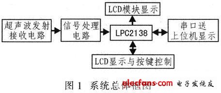
The system uses μC/OS-lI operating system. The system divides the software into four functional modules: echo A/D acquisition module, LED display and button processing module, LCD display module, alarm, storage and serial port processing module. The echo A/D acquisition module is used for sampling and saving real-time data; the LED display and button processing module is used to process the sampled data and convert it into meaningful parameters: the LCD display module is to put various parameters in the LED. Display; and the alarm, storage and serial port processing modules mainly process the corresponding data in real time. Figure 1 shows the overall block diagram of the system design.
3 system hardware design
3.1 Introduction to LPC2138 Microcontroller
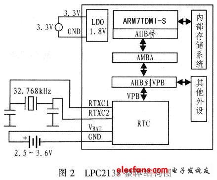
The LPC2138 embeds 512 KB of high-speed flash memory and 32 KB of RAM with abundant peripheral resources: two 32-bit timers (with capture and compare channels), two 10-bit 8-channel A/D converters, and one 10-bit D/A converter, PWM channel, 47 GPIOs, 9 edge or level triggered external interrupts, RTC with independent power and clock, multiple serial interfaces (UART, I2C, SPI, SSP). It contains a vectored interrupt controller that can be configured with interrupt priority and vector address. The on-chip boot loader can be implemented in system application programming (ISP/IAP), with an on-chip PLL that can achieve 60 MHz CPU operating frequency, with idle and Two low-power modes are powered down and can be woken up by an external interrupt. Figure 2 shows the overall structure of the LPC2138.
As the original Flip Clock maufacturer, factory has been in clock industry for over 20 years, with rich OEM experiences in clock, and great ability in new product R & D.
Our flip clock product lines including Flip Wall Clock, Flip Desk Clock, alarm flip clock, Flip Clock With Light, flip clock with seconds, etc, and almost all of our clocks accept customization in LOGO, designs, colors, functions, and package etc.
These flip clocks are not only our orginal designs, but owing patent protection in China, they have been widely sold to Europe countries, like The Netherlands, Spain, Italy, Germany, France, UK etc, Americas, Middle East and Asia like Japan, Korea etc.
These flip clocks are operated by batteries, driven by our self-developed powerful movement, time's showed by numbers, the left side is hour display card, and right side is minute display, time can be showed either in 12 hr or 24 hr, the number card falls down automatically every minute, the clock is working silently.
A nice clock and table display for home decoration, as well as good choice for corporate gift or business gift.
The number card is customizable to print corporate LOGO or company products as auto display.
It is for indoor use only, as the exposed gears and exposed flips need to be keep dry and clean.
Flip Clock
Flip Flop Wall Decor,Flip Clock,Chrome Wall Clock,Small Flip Clock Red
Guangzhou Huanyu Clocking Technologies Co., Ltd. , https://www.findclock.com