1 Introduction
In some devices or devices, it is desirable to communicate with each other between relatively rotating components, such as video signals, audio signals, control signals, sensing signals, and the like. The implementation methods of the rotating connection technology used today mainly include:
1) Fiber Optic rotary connector is used, but the device must be installed at the center of the rotating shaft or allow a small distance from the center. It is not applicable in some rotating shafts where hydraulic, pneumatic transmission and other wiring are required. Processing accuracy requirements are also higher;
2) Adopting a collector ring, but as the number of signal transmission lines increases, the number of collector rings needs to be increased accordingly, so that the reliability of signal transmission is reduced, and it is susceptible to environmental electromagnetic interference;
3) Non-contact signal transmission using optoelectronic coupling. At present, there are some schemes for realizing communication between relatively rotating components by infrared coupling, but infrared transmitting and receiving circuits and signal conversion circuits are integrated in the optocoupler plate and light The axial emission of the signal makes the rotating connector larger and difficult to apply in some places where space is limited.
In order to solve some shortcomings in the implementation method of the above rotating connection technology, a rotating signal transmission device based on photoelectric coupling technology is proposed. The rotating signal transmission device performs non-contact signal transmission between the relatively rotating components with light as a signal carrier, and uses a light-emitting diode (LED) and a photodiode as the light-emitting device and the light-receiving device, and the entire device has a simple structure and precision for machining. Low requirements, easy assembly and installation, and low cost.
2. Device composition and principle
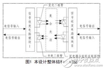
The device is composed of a signal transceiving circuit module I, a signal transceiving circuit module II, and a photoelectric coupling rotary connecting component, as shown in FIG. 1 .
2.1 Photoelectric coupling rotary joint parts
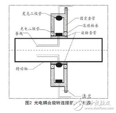
As shown in FIG. 2, the photoelectric coupling rotary connecting member is sleeved on the rotating shaft of the device, and the rotating sleeve is fixed to the rotating shaft to rotate together with the rotating shaft, and the fixing sleeve is connected with the fixed platform of the device through the flange structure. Considering that in the process of photoelectric transmission, external light radiation and reflected light of the LED on the inner wall of the sleeve also affect the reliability of signal transmission, so that the inner wall of the fixed sleeve is coated with a light absorbing coating to absorb external light radiation and reflected light.
2.1.1 Working principle
The rotating sleeve rotates together with the rotating shaft, so that the LED and the photodiode on the rotating sleeve and the fixed sleeve rotate relative to each other, and a 360-degree composite light field is formed in the cavity, so that the photodiode can be turned to any angle. Optical signals from the opposite LED tubes are received to enable signals to be transmitted at any rotational speed.
2.1.2 Determination of the number of LEDs and photodiodes
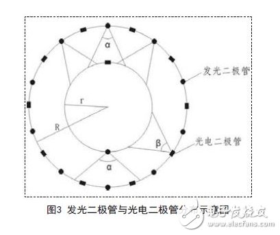
As shown in FIG. 3, if the full-angle of the LED light-emitting tube is known to be α, the full-angle of the photodiode is β, the radius of the inner wall of the fixed sleeve is R, and the radius of the outer wall of the rotating sleeve is r, and the photodiode on the fixed sleeve is provided. The number is n, the critical quantity is Q1, the number of LED light-emitting tubes on the fixed sleeve is m, and the critical quantity is Q2, then the critical quantity Q1, Q2 should satisfy the following relationship:
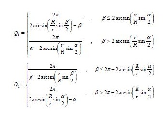
At the same time, the two channels of optical signals should not interfere with each other and should also meet the constraint condition: r / R "sin (α / 2).
In order to make the signals transmit signals in a bidirectional transmission, the number of LEDs on the fixed sleeve is greater than [Q2], and the number of photodiodes is greater than [Q1], where [Q1], [Q2] represents the integer part of Q1 and Q2, respectively.
Enhanced Bending Insensitive Single Mode Fiber
Shandong Qingguo Fiber Factory, Single Mode Fiber, Enhanced Bending Insensitive Single Mode Fiber
Shandong Qingguo Optical Fiber Co., Ltd. , https://www.qgfiber.com