DC/DC is a switching power supply chip. Switching power supply refers to the characteristics of energy storage using capacitors and inductors. The high-frequency switching operation is performed by a controllable switch (MOSFET, etc.), and the input electric energy is stored in the capacitor (sensing). When the switch is turned off, the electric energy is released. Provide energy to the load. The power or voltage capability of the output is related to the duty cycle (the ratio of the on-time of the switch to the period of the entire switch). Switching power supplies can be used for boost and buck. There are two types of DC-DC products we use. One is a charge pump (Charge Pump), and the other is an inductive energy storage DC-DC converter. This article details the knowledge of these two DC/DC products.
Compared with the core voltage requirements of 2.8V~3.3V in previous years, more and more chips can be operated smoothly at low voltages of 1.2V~1.8V. Thus, in a portable product that mainly uses a lithium (polymer) battery or a nickel-hydrogen battery as a system operating energy, selecting a suitable voltage converter has become a factor that designers need to consider. Low-dropout linear regulator (LDO) has a larger drop in input voltage and output low voltage due to lower operating voltage. Linear regulators generate a large amount of energy loss during voltage conversion, so that their efficiency is even May be as low as 50% or less. More designers are beginning to favor buck DC/DC converters.
For the consideration of inductance selection in DC/DC switching converters, the size, equivalent resistance and current capacity usually determine the choice of inductance, and may also include design factors such as cost, delivery time and technical support; It is generally considered that under the same conditions, in order to reduce the internal loss of the inductor device, an inductor having a smaller ESR (Equivalent Series Resistance) value is preferred. But the actual situation needs more consideration, this article tries to give a better compromise.
The components of the inductor that can produce inductance are collectively referred to as inductors, often referred to simply as inductors. It works by the principle of electromagnetic induction. Function: Resisting AC and DC, blocking high frequency through low frequency (filtering), that is to say, high frequency signal will encounter great resistance when passing through the inductor, it is difficult to pass, and the resistance when the low frequency signal passes through it Smaller, that is, low frequency signals can pass through it more easily. The resistance of the inductor to DC is almost zero. The inductance is the ratio of the magnetic flux around the inside of the wire when the alternating current is passed through the wire, and the magnetic flux of the wire is the current that produces the flux. When a direct current is passed through the inductor, only a fixed magnetic line of force is present around it, which does not change with time; however, when an alternating current is passed through the coil, magnetic lines of force appearing around it will appear around the time. According to Faraday's law of electromagnetic induction - magnetoelectricity, the varying magnetic lines of force produce an induced potential across the coil, which is equivalent to a "new power source". When a closed loop is formed, this induced potential generates an induced current. It is known by Lenz's law that the total amount of magnetic lines generated by the induced current is intended to prevent changes in the magnetic lines of force.
The loss of the inductor comes from its DC resistance (Rdc) and AC impedance (Rac). The DC impedance is determined by the wire diameter of the coil and the length of the coil. The AC impedance is the eddy current loss caused by the magnetic flux leakage between the ferrite core and the GAP portion and the copper wire. Generally, when DC/DC is working, consider the current flowing through the inductor and the DC current loss.
The missing portion is represented by Rdc & TImes; Idc; the portion lost to the alternating current is characterized by Rac & TImes; ΔI. In the case where the current flow amplitude ΔI of the inductor is large and Idc is small, even if the DC impedance is small, if the AC impedance is large, its efficiency is lowered; on the contrary, even if the DC impedance is large, the AC impedance is small. Its efficiency is also likely to rise.
When the inductor output current (Iout) is small, the average current through the inductor is very small, and the loss of the DC impedance portion is small when the DC impedance Rdc is slightly different, but the difference in current amplitude (ΔI) affects the AC impedance. Part of the lost power. When Iout is large, the average current through the inductor is large, and the difference in DC resistance Rdc causes a large loss difference, and the power loss of the AC impedance is not the main factor.
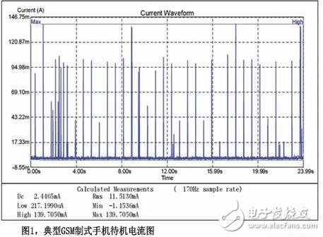
Figure 1 is a waveform diagram of the current consumption of a GSM mobile phone in standby mode, where the Idc is small and the current flow amplitude ΔI is large. Based on the above conclusions, the average standby current is reduced from 2.4465mA to 2.1337mA. The average standby current is reduced by 12.8%, which means that the standby time of the mobile phone can be extended by 14.7%. Then the DC resistance is small. In terms of inductance, how is its value reflected? It is suitable for the working mode where the Idc is large and the current flow amplitude ΔI is small. This is the working environment in which the portable product is used when the user uses functions such as call, multimedia play, game, GPS navigation, etc., and DC impedance can be expected at this time. Smaller inductors will result in longer usage times. However, since the average current is relatively large, a certain degree of improvement does not cause much difference in actual usage time. Instead, we believe that the temptation of longer standby time can make the designer sacrifice the time of use.
The next-generation digital processors for 3G are evolving to 90nm and 65nm process technologies, which will reduce the power supply to nearly 1V, and we will see more DC/DC converters in system-level power supply designs. Figure. The balance between standby time and usage time is one of the trade-offs that designers need to face constantly in the design process, and the important impact on standby time deserves careful selection of inductors.
When it comes to lighting, outdoor as well as Indoor Lighting is also a concern. Outdoor wall lights are in great demand. LED street lights, garden lights and all outdoor lights including parking lot lights are innovated to meet the high market demand. To compete with the best markets, LEDER has developed a range of outdoor wall lights, which are perfect for lighting a wide variety of outdoor applications. The exterior of the building or any living space associated with it should be very carefully accommodated, as the exterior areas reflect the atmosphere and aesthetics of the interior. Outdoor wall lights should be selected carefully as they help to form the expected first impression of the entire spatial area. For example, carefully arranged garden lights and street lights not only have a strong structure to withstand all weather conditions and influence factors, achieving the effect of safety is crucial, but also have rich shapes to help beautify gardens and lawns.
• 50,000 hour expected lifetime
• 3 year warranty
• Shatter proof diffusers
• Low glare lighting
Outdoor Wall Light
Outdoor Sconces,LED Wall Pack,Solar Wall Lights,Exterior Wall Lights
JIANGMEN LEDER LIGHTING CO., LTD , https://www.lederlight.com