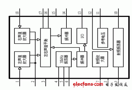
Internal block diagram of MB1404
This article refers to the address: http://


The above is the use of MB1404 as a stereo composite signal transmitter, you can use the internal high-frequency amplifier and oscillator can also be used! According to my experience, it is recommended that beginners use the typical recommended three-point oscillating circuit using the internal high-frequency part. If you are a high-frequency master who has already used a certain strength, I still recommend using a high-stability crystal oscillator. The device is used to stabilize the transmission frequency, but the general crystal oscillator has a problem that the modulation frequency is too small. If possible, it is recommended to use a PLL frequency synthesizer. In that case, you have a personal (illegal) station that wants a professional radio station. Ha! But for your legal use and easy to get started, I will share the simplest application with everyone. If you want more information, you can communicate directly with me.
The BA1404 is one of the few FM transmitter ICs that compensates for the inadequacy of designing FM circuits with discrete components in the past and has stereo modulation. A beautiful stereo FM signal can be obtained with only a few external components. Therefore, it has important application value in FM stereo transmission and wireless microwave.
1. Main features of BA1404
The main features of the BA1404 are as follows:
â— Low voltage, low power design, voltage between 1 ~ 3V, typical value is 1.25V, maximum power consumption is 500mW, quiescent current is 3mA;
â— Integrate stereo modulation, FM modulation, and RF amplification circuits on one chip;
â—There are fewer peripheral components required;
â—The separation of the two channels is high, with a typical value of 45dB;
◠Input impedance is 540Ω (fin=1kHz), input gain is 37dB (Vin=0.5mV);
â— Typical RF output voltage is 600mV.
2. Pin function and working principle
The BA1404 is mainly composed of a front audio amplifier (AMP), a stereo modulator (MPX), an FM modulator and a radio frequency amplifier.
The stereo preamps are two channel audio amplifiers. With an input of 0.5mV, the gain is up to 37dB and the bandwidth is 19kHz. If there is a component with a frequency higher than 19 kHz in the input signal, a low-pass filter must be added to the input, otherwise the separation of the two channels will decrease.
In the stereo modulation group, the 38 kHz signal from the oscillator output is stereo modulated. Usually an adjustable resistor is connected to pins 16 and 17 for optimum channel separation.
The modulated signal synthesized by the stereo mixed signal (MPX output signal) and the pilot output signal (PILOT OUT) enters the RF oscillator through 12 feet and FM is modulated by the carrier, and the RF signal is output after being amplified by the RF. The typical value of the RF signal is About 600mV.
A reference voltage unit VREF is also provided inside the BA1404. The designer can use this voltage signal to change the capacitance value of the external varactor, and then change the oscillation frequency of the carrier. Therefore, as long as the voltage division value of a resistor is controlled, the purpose of changing the transmission frequency can be achieved, which is a relatively unique design.
3. Typical application
The picture shows a typical application circuit of the BA1404. In the figure, the left and right channels are each input into the BA1404 through a pre-emphasis circuit. The internal reference voltage is used to change the capacitance value of the varactor to adjust the transmission frequency.
Pay attention to the following points when designing:
(1) In order to be able to match the frequency response of the transmitter and the FM receiver, a pre-emphasis network is added at the input end with a time coefficient of 50 μs.
(2) At the 13th and 14th feet, when the stereo mixed signal and the pilot signal output from the stereo modulator are combined, the separation of the stereo channel may be deteriorated, so the values ​​of the peripheral components of the 12, 13, and 14 pins must be noted.
(3) If the output frequency range of the OSC oscillation network is in the range of 76 to 108 MHz, it can be wound around 2.5 turns of the 0.5 mm enameled wire on the core of ?5 mm, so that the capacitance value of C11 is 47 pF. The same should be true for the RF matching network on pin 7.
(4) In order to simplify the application, the following measures can be taken:
â— Leave the 16 and 17 feet floating. Since the integrated channel has already ensured a high degree of channel separation, the adjustable resistor is only optimized.
â— Do not use the varactor to fine tune the transmission frequency and directly short-circuit at the varactor. This way, R3 and D1 can be omitted.
â— The RF matching network on pin 7 can be omitted and directly connected to VCC.
Unique design - compatible with films taken with Instax Series Camera, Pringo P231, Instax SP-1 SP-2, Polaroid PIC-300 Z2300 Snap Touch, LG PD 233 239, Leica Sofort, HP Sprocket, Kodak Mini Mobile Wi-Fi & NFC Photo Printer...
Fashionable and cute appearance designed instax book album . PVC or Kraft paper material, reliable and durable.
Lightweight and soft handy album can be carried in your bag to show your best instant photos or put it home as a decoration, also perfect as a gift. Preserve every happy memories in your life.
Practical design and exquisite workmanship, combination practicability with popular fashion.
Photo Album,Calendar Photo Album,Polaroid Photo Album,Photo Record Book
GuangZhou CAIUL Digital Products CO,.LTD. , https://www.caiul-instax.com